











OR Gate Using NOR Gate
An OR logic Gate can be made using NOR logic gates. As we know, NOR is a universal logic gate, meaning it can be used to build other basic logic gates such as NOT, OR, AND, NAND, XOR, and XNOR. Implementing an OR gate using a NOR gate is useful when you need an OR logic circuit but only have NOR gates available; an OR logic gate is unavailable.
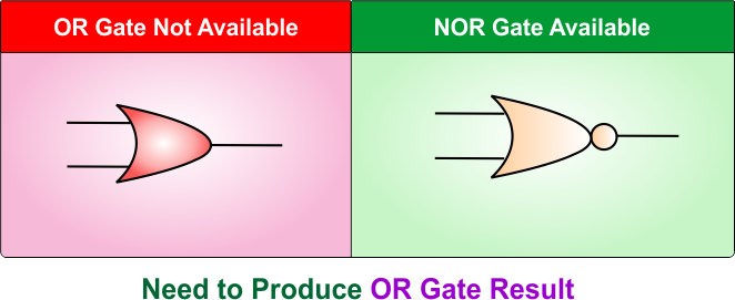
OR logic gate and a NOR logic gate, both are different in terms of output. so we have to implement NOR gate in such a way that its results are exactly similar to an OR logic gate.
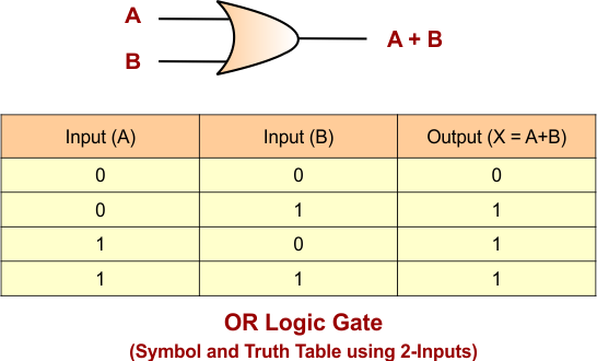
OR Logic Gate
An OR logic gate produces the output 1 (High) when at least one input is 1 (High). Output will becomes 0 (LOW) only the case when all inputs are 0 (LOW). OR logic gate truth table and its symbols are given below
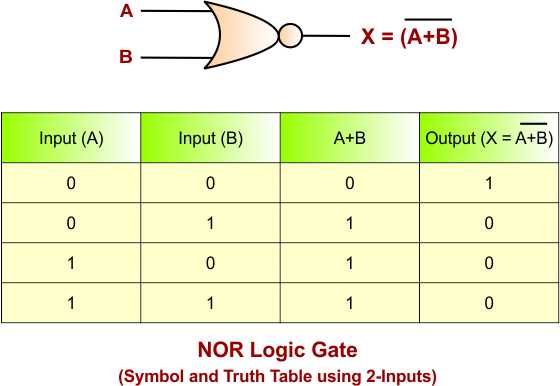
NOR Logic Gate
NOR is a universal logic gate that is widely used in digital logic design to perform NOT-OR operation; it gives a HIGH output (1) when all inputs are LOW (0). If any input is HIGH (1), then the output becomes (0).
If we want to construct an OR gate which contains a various number of inputs, then various numbers of NOR gates are required to implement this process. Let’s discuss various cases
OR Gate Using NOR Gate: 2-Input
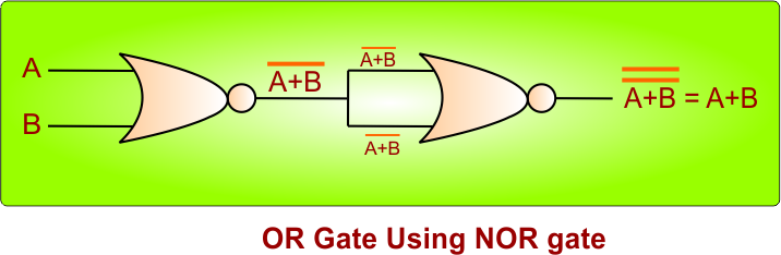
If we want to construct a 2-input OR logic gate using NOR gates, then 2 NOR gates are required to implement this process.
- First NOR gate: Inputs are A and B, and its output is (A+B)’
- Second NOR gate: The output of the first NOR gate (A+B)’ is the input of the second NOR gate at both ends:
The following diagram explains the process
OR Gate Using NOR Gate: 3-Input
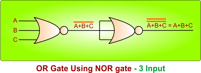
If we want to construct a 3-input OR logic gate using NOR gates, then 2 NOR gates are required to implement this process.
- First NOR gate: Inputs are A, B, and C, and its output is (A+B+C)’.
- Second NOR gate: The output of the first NOR gate (A+B+C)’ is the input of the second NOR gate at both ends:
The following diagram explains the process
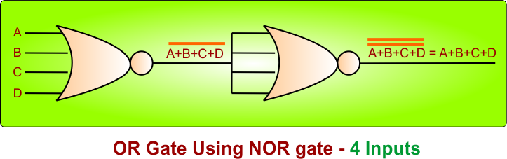
OR Gate Using NOR Gate: 4-Input
If we want to construct a 4-input OR logic gate using NOR gates, then 2 NOR gates are required to implement this process.
- First NOR gate: Inputs are A, B, C, and D, and its output is (A+B+C+D)’
- Second NOR gate: The output of the first NOR gate (A+B+C+D)’ is the input of the second NOR gate at both ends:
The following diagram explains the process