












Introduction to Logic Gates
Logic Gates are the building blocks of computer systems and digital electronics. The electronic circuits perform logical operations on one or many binary inputs and produce a single binary output. So, we can say that logical gates work with binary values (0,1)
A logical gate takes one or more binary inputs and produces a single binary output according to a specific logical rule which applied over logic gate.

Logic gates can be represented using Symbols, Boolean expressions, and Truth Tables.
Logic Gates are mainly used in computers, smartphones, digital watches, calculators, CPUs, memory, and communication systems. To understand digital electronics, computer architecture, and electronic circuit design, logic gates are very important to learn
Binary Values in Logic Gates
Logic gates only work with binary values. The following table shows binary values with their meaning
| Binary Value | Logic State | Meaning |
|---|---|---|
| 0 | LOW | False / OFF |
| 1 | HIGH | True / ON |
For example,
- if an input is 1, it represents a HIGH or ON state.
- If an input is 0, it represents a LOW or OFF state.
Types of Logic Gates
Logic Gates are of several types; the following diagram shows them
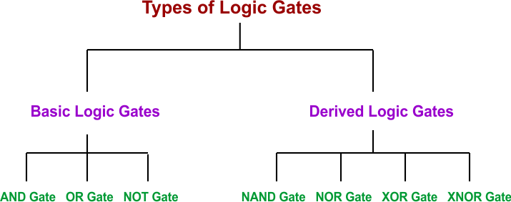
The AND, OR, and NOT gates are considered basic logic gates, while NAND, NOR, XOR, and XNOR are known as derived or special-purpose gates.
Let’s explain each gate with its definition, Boolean expression, and truth table
1. AND Gate
AND Logic Gate give output 1 only when all inputs are 0. If even one input is 0 then output beceomes 0.
Boolean Expression:
Here is the Boolean expression for a two-input AND gate.
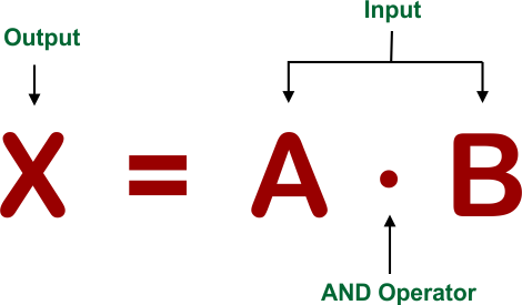
In the above Boolean expression, A and B are inputs, X is the output, and (.) is the AND operator. Dot sign (.) represents the AND Gate
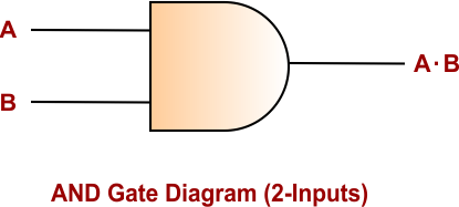
Diagram for AND Gate
Here is the simple diagram for AND Gate where A, B are inputs and A.B is the output
Truth Table of AND Gate
AND gate Truth table for two input variables is given below
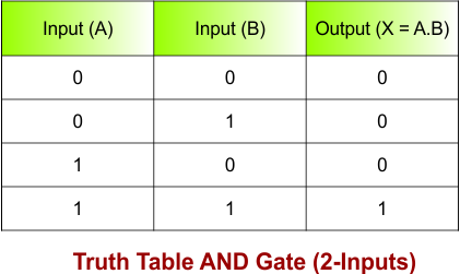
In the above truth table of AND Gate
- For A = 0, B = 0, the output will be 0.
- For A = 0, B = 1, the output will be 0.
- For A = 1, B = 0, the output will be 0.
- For A = 1, B = 1, the output will be 1.
2. OR Gate
OR Logic Gate gives output 0 only when all inputs are 0. If even one input is 1, then output becomes 1. Plus Sign (+) represents OR Gate
Boolean Expression:
Here is the Boolean expression for a two-input OR gate.
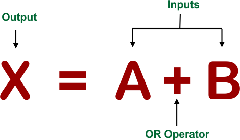
In the above Boolean expression, A and B are inputs, X is the output, and (+) is the OR operator. Plus sign (+) represents the AND Gate
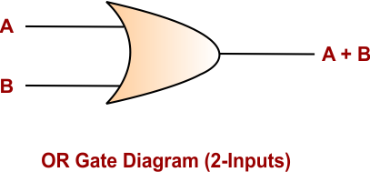
Diagram for OR Gate
Here is the simple diagram for OR Gate where A, B are inputs and A+B is the output
Truth Table of OR Gate
OR gate Truth Table for two input variables is given below
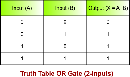
In the above truth table of OR Gate
- For A = 0, B = 0, the output will be 0.
- For A = 0, B = 1, the output will be 1.
- For A = 1, B = 0, the output will be 1.
- For A = 1, B = 1, the output will be 1.
3. NOT Gate
NOT Logic Gate is also called an inverter, which takes a single input and converts it into an output that is opposite of input. Bar Sign over input symbol (-) represents the NOT Gate
- For input 0, output becomes 1.
- For input 1, output becomes 0.
Boolean Expression:
Here is the Boolean expression for a NOT gate.
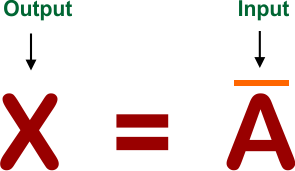
In the above Boolean expression, A is the input, X is the output, and (+) is the OR operator. Bar sign (-) represents the NOT Gate
Diagram for NOT Gate
Here is the simple diagram for NOT Gate where A is input and A̅ is the output
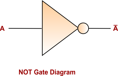
Truth Table of NOT Gate
NOT Gate Truth Table using two inputs is given below
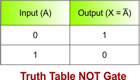
For input 0, output becomes 1 and similarly, for input 1 output becomes 0.
4. NAND Gate
NAND gate (Not-AND Gate) is digital logic gate which produce output “0” only when all inputs are “1”. In all other cases, the output remains “1”. It is also called inverted AND gate becuase it reverse the output of AND Gate.
Boolean Expression
Here is the Boolean expression for a NAND gate.
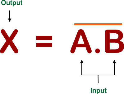
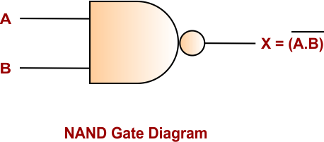
Diagram for NAND Gate
Here is the simple diagram for NAND Gate using two inputs is given below
Truth Table of NAND Gate
The Truth table of the NAND gate using two inputs is given below
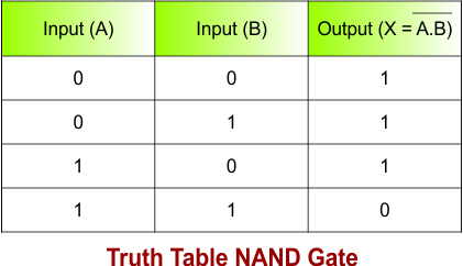
In the above truth table of NAND Gate
- For A = 0, B = 0, the output will be 1.
- For A = 0, B = 1, the output will be 1.
- For A = 1, B = 0, the output will be 1.
- For A = 1, B = 1, the output will be 0.
NAND is known as a universal gate because basic logic gates can be constructed using only NAND gates.
5. NOR Gate
NOR Logic gate (Not-OR Gate) is digital logic gate which produce output “1” only when all inputs are “0”. In all other cases, the output remains “0”. It is also called inverted OR gate becuase it reverse the output of OR Gate.
Boolean Expression
Here is the Boolean expression for a NOR gate.
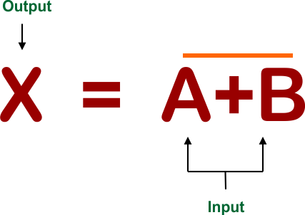
Diagram for NOR Gate
Here is the simple diagram for NOR Gate using two inputs is given below
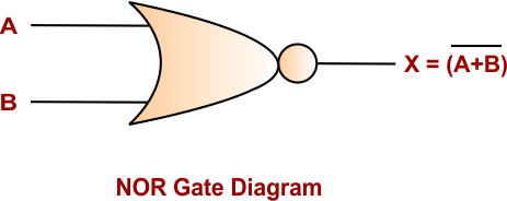
Truth Table of NOR Gate
The NOR Gate Truth table of using two inputs is given below
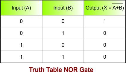
In the above truth table of NOR Gate
- For A = 0, B = 0, the output will be 1.
- For A = 0, B = 1, the output will be 0.
- For A = 1, B = 0, the output will be 0.
- For A = 1, B = 1, the output will be 0.
NOR is also a universal gate, meaning other basic logic gates can be built using NOR gates.
6. XOR Gate
The XOR (Exclusive OR) gate produces an output of 1 when the inputs are different.
Boolean Expression
Here is the Boolean expression for a XOR gate using two inputs
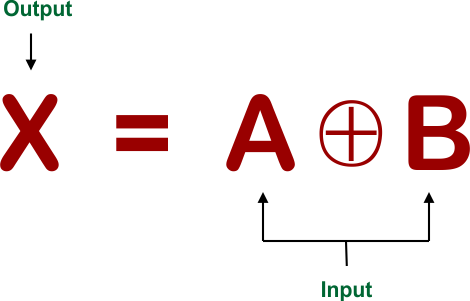
Diagram for XOR Gate
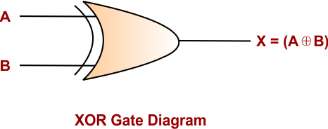
Here is the simple diagram for XOR Gate using two inputs
Truth Table of XOR Gate
The Truth table of the XOR gate using two inputs is given below
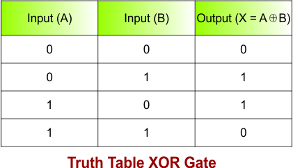
In the above truth table of OR Gate
- For A = 0, B = 0, the output will be 0.
- For A = 0, B = 1, the output will be 1.
- For A = 1, B = 0, the output will be 1.
- For A = 1, B = 1, the output will be 0.
For example, if A = 0 and B = 1, the XOR output is 1.
7. XNOR Gate
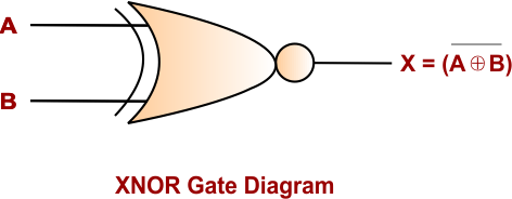
The XNOR (Exclusive NOR) gate is the opposite of XOR. It produces an output of 1 when the inputs are the same.
Boolean Expression:
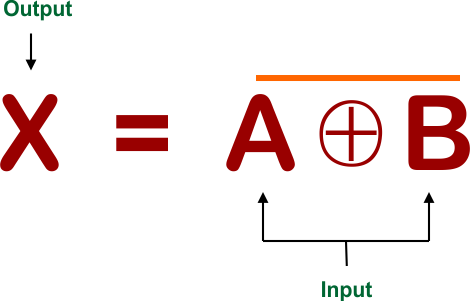
Diagram for XNOR Gate
Here is the simple diagram for XNOR Gate using two inputs
Truth Table of XNOR Gate
The Truth table of the XNOR gate using two inputs is given below
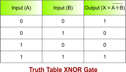
In the above truth table of OR Gate
- For A = 0, B = 0, the output will be 1.
- For A = 0, B = 1, the output will be 0.
- For A = 1, B = 0, the output will be 0.
- For A = 1, B = 1, the output will be 1.
Logic Gates Truth Table
The following truth table shows a quick overview of all logic gates using two-input
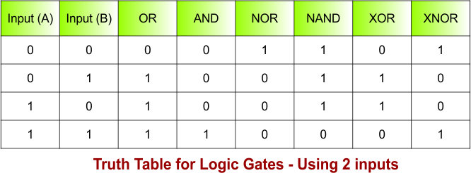
NOTE: NOT gate works with a single input, so it is not added in the above truth table
Implement all Gates using NOR Gate
All Logic Gates (NOT, AND, OR, NOR, XOR, XNOR) can be implemented by using only NOR Gate. It is possible becuase of NOR Gate is a universal Logic Gate; it means only NOR gate can implement many other logic gates. Here is a simple explanation of how each logic gate can be implemented using a NOR Gate.
The symbol of the NOR Gate is given below
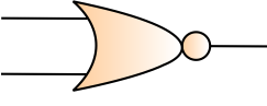
Let’s implement all logic gates using this symbol
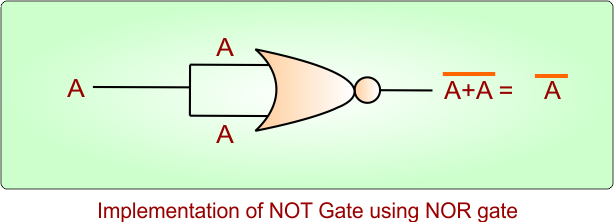
Implementation of NOT Gate using NOR gate
The input-to-output results in the following diagram are exactly the same as a NOT Gate. It is done through NOR Gate
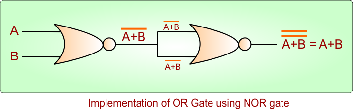
Implementation of OR Gate using NOR gate
The input-to-output results in the following diagram are exactly the same as an OR Gate. It is done through NOR Gate
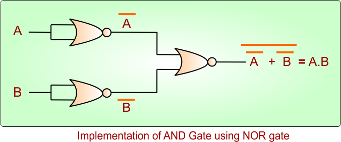
Implementation of AND Gate using NOR gate
The input-to-output results in the following diagram are exactly the same as an OR Gate. It is done through NOR Gate
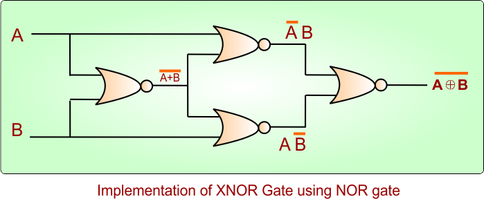
Implementation of XNOR Gate using NOR gate
The input-to-output results in the following diagram are exactly the same as an XNOR Gate. It is done through NOR Gate
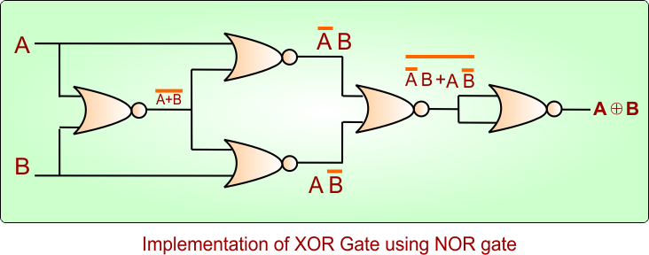
Implementation of XOR Gate using NOR gate
The input-to-output results in the following diagram are exactly the same as an XOR Gate. It is done through NOR Gate
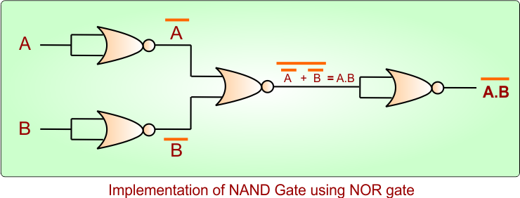
Implementation of NAND Gate using NOR gate
The input-to-output results in the following diagram are exactly the same as an NAND Gate. It is done through NOR Gate
Implement all Gates using NAND Gate
All Logic Gates (NOT, AND, OR, NOR, XOR, XNOR) can be implemented by using only NAND gates. It is possible becuase of NAND Gate is a universal Logic Gate; it means only NAND can implement many other logic gates. Here is a simple explanation of how each logic gate can be implemented using a NAND Gate.
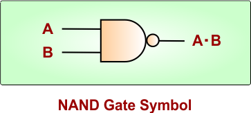
The symbol of the NAND Gate is given below
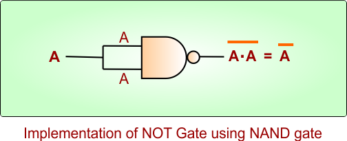
Implementation of NOT Gate using NAND gate
The input-to-output results in the following diagram are exactly the same as an NOT Gate. It is done through NAND Gate
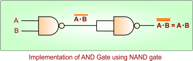
Implementation of AND Gate using NAND gate
The input-to-output results in the following diagram are exactly the same as an AND Gate. It is done through NAND Gate
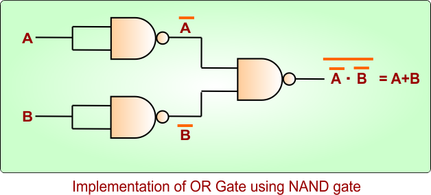
Implementation of OR Gate using NAND gate
The input-to-output results in the following diagram are exactly the same as an OR Gate. It is done through NAND Gate
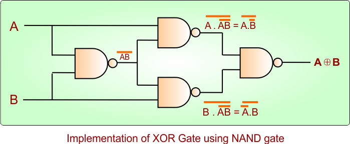
Implementation of XOR Gate using NAND gate
The input-to-output results in the following diagram are exactly the same as an XOR Gate. It is done through NAND Gate
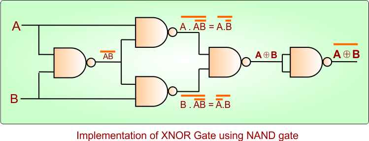
Implementation of XNOR Gate using NAND gate
The input-to-output results in the following diagram are exactly the same as an XNOR Gate. It is done through NAND Gate
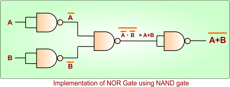
Implementation of NOR Gate using NAND gate
The input-to-output results in the following diagram are exactly the same as an NOR Gate. It is done through NAND Gate
Other Logic Gates / Logic Elements
Besides the basic logic gates, several other logic elements are used to control, process, and transmit digital signals in electronic circuits.
| Logic Gate / Logic Element | Description |
|---|---|
| Buffer Gate | Produces the same output as its input. If the input is 1, the output is 1; if the input is 0, the output is 0. |
| Tri-State Buffer | Has three output states: 0, 1, and High-Impedance (Z). It is commonly used in digital buses. |
| Schmitt Trigger | Converts a slowly changing or noisy input signal into a clean digital signal using two threshold levels. |
| Transmission Gate | Acts as a controlled electronic switch that allows a signal to pass or blocks it. |
Why Are Logic Gates Important?
Logic gates are important because they form the foundation of digital logic circuits. By combining different logic gates, engineers can design more complex digital systems.
Logic gates are used to build:
- Adders and subtractors
- Multiplexers and demultiplexers
- Encoders and decoders
- Flip-flops
- Registers
- Counters
- Memory circuits
- Arithmetic Logic Units (ALUs)
- Computer processors
Applications of Logic Gates
Logic gates are widely used in modern electronic and computing devices. Some common applications include:
1. Computers
Logic gates are essential components of CPUs and other computer hardware. They help perform arithmetic, comparison, and decision-making operations.
2. Memory Systems
Digital memory circuits use logic gates to store and process binary information.
3. Control Systems
Logic gates can be used to control electronic devices based on specific input conditions.
4. Communication Systems
Digital communication equipment uses logic circuits to process and manipulate binary data.
5. Digital Electronics
Logic gates are fundamental components in calculators, digital clocks, smartphones, and other electronic devices.
Logic Gates vs Boolean Algebra
Logic gates and Boolean algebra are closely related concepts used in digital electronics. Logic gates are physical electronic circuits that perform logical operations, while Boolean algebra is a mathematical system used to represent and simplify those operations.
Frequently Asked Questions (FAQs)
What is a logic gate?
A logic gate is a digital electronic circuit that performs a logical operation on binary inputs and produces a binary output.
What are the basic logic gates?
The three basic logic gates are AND, OR, and NOT.
What are universal logic gates?
NAND and NOR are called universal gates because any basic logic gate can be constructed using only NAND gates or only NOR gates.
How many basic types of logic gates are commonly studied?
Seven commonly studied logic gates are AND, OR, NOT, NAND, NOR, XOR, and XNOR.
What are the two values used by logic gates?
Logic gates use two binary values: 0 and 1, which generally represent LOW and HIGH logic states.