












4 Input XNOR Gate
A 4-input XNOR gate is a digital logic gate with 4 inputs and 1 output.
- The output is HIGH (1) when an even number of inputs are HIGH (1).
- The output is LOW (0) when an odd number of inputs are HIGH (1).
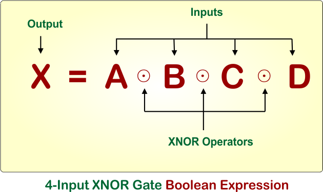
Example: For four inputs, there will be 4 variables (i.e., A, B, C, and D), and the output is represented by the variable X. The Boolean expression for a 4-input XNOR logic gate is X = A ⊙ B ⊙ C ⊙ D.
Notations of 4-input XNOR gate
The 4-input XNOR gate can be represented using the following notations:
- XNOR notation:
A ⊙ B ⊙ C ⊙ D - Complemented XOR notation:
(A ⊕ B ⊕ C ⊕ D)' - Boolean notation:
A'B'C'D' + A'B'CD + A'BC'D + A'BCD' + AB'C'D + AB'CD' + ABC'D' + ABC
Let’s explain the 4-input XNOR logic gate symbol, Boolean expression, and Truth Table.
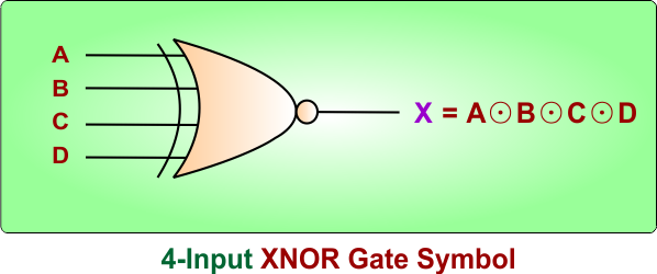
4-Input XNOR Gate Symbol
The 4-input XNOR gate symbol has four input terminals, represented by A, B, C, and D. The output is represented by X. The following diagram shows the result
4-Input XNOR Gate Boolean Expression
The following diagram shows the Boolean expression of a 4-input XNOR gate.
4-Input XNOR Gate Truth Table
The 4-input XNOR logic gate truth table shows the output for all possible combinations of the inputs A, B, C, and D. The output X becomes HIGH (1) when an even number of inputs are HIGH (1). The output becomes LOW (0) when an odd number of inputs are HIGH (1).
The 4-input XNOR gate has 2⁴ = 16 possible input combinations.
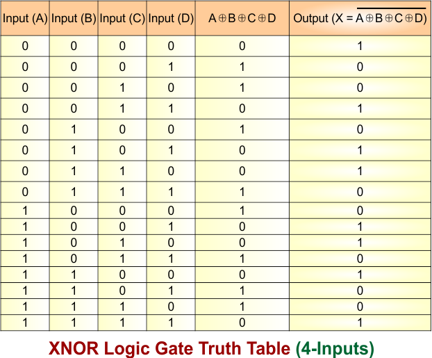
Let’s explain the truth table of a 4-input XNOR logic gate.
- A = 0, B = 0, C = 0, D = 0: No input is HIGH, so the output is 1 (HIGH).
- A = 0, B = 0, C = 0, D = 1: Only input D is HIGH, so the output is 0 (LOW).
- A = 0, B = 0, C = 1, D = 0: Only input C is HIGH, so the output is 0 (LOW).
- A = 0, B = 0, C = 1, D = 1: Inputs C and D are HIGH, so the output is 1 (HIGH).
- A = 0, B = 1, C = 0, D = 0: Only input B is HIGH, so the output is 0 (LOW).
- A = 0, B = 1, C = 0, D = 1: Inputs B and D are HIGH, so the output is 1 (HIGH).
- A = 0, B = 1, C = 1, D = 0: Inputs B and C are HIGH, so the output is 1 (HIGH).
- A = 0, B = 1, C = 1, D = 1: Inputs B, C, and D are HIGH, so the output is 0 (LOW).
- A = 1, B = 0, C = 0, D = 0: Only input A is HIGH, so the output is 0 (LOW).
- A = 1, B = 0, C = 0, D = 1: Inputs A and D are HIGH, so the output is 1 (HIGH).
- A = 1, B = 0, C = 1, D = 0: Inputs A and C are HIGH, so the output is 1 (HIGH).
- A = 1, B = 0, C = 1, D = 1: Inputs A, C, and D are HIGH, so the output is 0 (LOW).
- A = 1, B = 1, C = 0, D = 0: Inputs A and B are HIGH, so the output is 1 (HIGH).
- A = 1, B = 1, C = 0, D = 1: Inputs A, B, and D are HIGH, so the output is 0 (LOW).
- A = 1, B = 1, C = 1, D = 0: Inputs A, B, and C are HIGH, so the output is 0 (LOW).
- A = 1, B = 1, C = 1, D = 1: All four inputs are HIGH, so the output is 1 (HIGH).
4-Input XNOR Gate – Timing Diagram
4-input XNOR gate timing diagram showing the relationship between inputs A, B, C, D, and output X in a digital logic circuit. The diagram illustrates the logic-level transitions of four inputs (A, B, C, and D) and one output (X) over time.
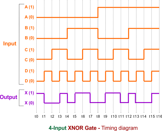
- Input A: Initially remains at logic 0, then changes to 1 midway through the timing interval and stays high.
- Input B: Alternates between logic 0 and 1 at longer time intervals.
- Input C: Toggles between 0 and 1 more frequently than A and B.
- Input D: Alternates between logic 0 and 1 at a different timing pattern.
- Output X: Becomes 1 (HIGH) when an even number of inputs are 1. It becomes 0 (LOW) when an odd number of inputs are 1.
The vertical dotted lines segment the diagram into equal time intervals, allowing for straightforward comparison between input transitions and the corresponding output behavior.