












4 Input OR Gate
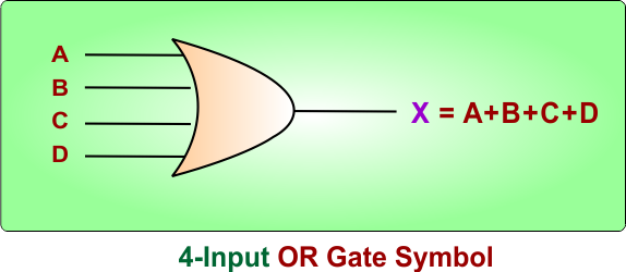
A 4-input OR gate is a digital logic gate that contains 4 inputs and one output.
- The output will be HIGH (1) when at least one input is HIGH (1)
- The output will be LOW (0) when all inputs are LOW (0)
Example: For four inputs, there will be 4 variables (i.e., A, B, C, D) that may be used, and the output is also represented by a variable as “X”. The Boolean expression for a 4-input OR logic gate will be X = A+B +C+D.
Let’s explain the 4-input OR logic gate symbol, Boolean expression, and Truth Table
4-Input OR Gate Symbol
The 4-Input OR logic gate symbol can be represented using four input terminals (taken as inputs), which are given in the following diagram as A, B, C, and D. The output is represented by “X”.
4-Input OR Gate Using Three 3-Input OR Gates
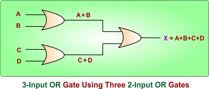
The 4-Input OR logic gate symbol can be represented using Three 2-input OR gates; each OR gate contains 2 inputs instead of 3.
- First OR gate: Inputs A and B, and produces the output A + B.
- Second OR gate: Inputs C and D, and produces the output C + D.
- Third OR gate: The outputs of the two OR gates will be given to the inputs of the third OR gate, which produces the result A + B + C + D.
The following diagram explains the process
4-Input OR Gate Boolean Expression
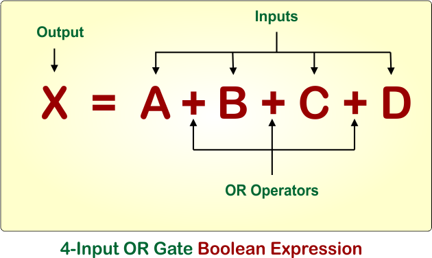
The Boolean expression of a 4-input OR gate with inputs A, B, C, and D and output X is:
- X = A + B + C + D
Here, the + symbol represents the OR operation. The following diagram shows the Boolean expression of a 4-input OR gate
4-Input OR Gate Truth Table
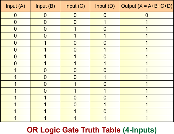
The 4-input OR logic gate truth Table shows the output for all possible combinations of inputs A, B, C, and D. The output X becomes HIGH (1) when at least one input is HIGH (1). The output (“X”) becomes LOW (0) only in the case when all inputs are LOW (0).
The following diagram shows the truth table of a 4-input OR logic gate
Let’s explain the truth table of a 4-input OR logic gate:
- A = 0, B = 0, C = 0, D = 0: All inputs are LOW, so the output is 0 (LOW).
- A = 0, B = 0, C = 0, D = 1: D is HIGH (1), so the output is 1 (HIGH).
- A = 0, B = 0, C = 1, D = 0: C is HIGH (1), so the output is 1 (HIGH).
- A = 0, B = 0, C = 1, D = 1: C and D are HIGH (1), so the output is 1 (HIGH).
- A = 0, B = 1, C = 0, D = 0: B is HIGH (1), so the output is 1 (HIGH).
- A = 0, B = 1, C = 0, D = 1: B and D are HIGH (1), so the output is 1 (HIGH).
- A = 0, B = 1, C = 1, D = 0: B and C are HIGH (1), so the output is 1 (HIGH).
- A = 0, B = 1, C = 1, D = 1: B, C, and D are HIGH (1), so the output is 1 (HIGH).
- A = 1, B = 0, C = 0, D = 0: A is HIGH (1), so the output is 1 (HIGH).
- A = 1, B = 0, C = 0, D = 1: A and D are HIGH (1), so the output is 1 (HIGH).
- A = 1, B = 0, C = 1, D = 0: A and C are HIGH (1), so the output is 1 (HIGH).
- A = 1, B = 0, C = 1, D = 1: A, C, and D are HIGH (1), so the output is 1 (HIGH).
- A = 1, B = 1, C = 0, D = 0: A and B are HIGH (1), so the output is 1 (HIGH).
- A = 1, B = 1, C = 0, D = 1: A, B, and D are HIGH (1), so the output is 1 (HIGH).
- A = 1, B = 1, C = 1, D = 0: A, B, and C are HIGH (1), so the output is 1 (HIGH).
- A = 1, B = 1, C = 1, D = 1: All inputs are HIGH (1), so the output is 1 (HIGH).
4-Input OR Gate – Timing Diagram
4-input OR gate Timing diagram showing the relationship between inputs A, B, C, D, and output X in a digital logic circuit.
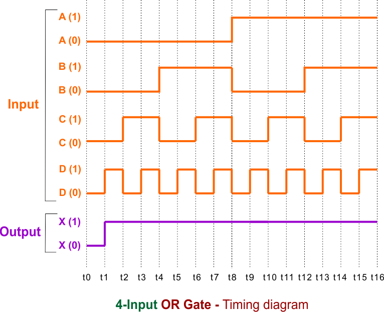
- Input A: Initially remains at logic 0, then changes to 1 midway through the timing interval and stays high.
- Input B: Alternates between logic 0 and 1 at longer time intervals.
- Input C: Toggles between 0 and 1 more frequently than A and B.
- Input D: Switches between logic 0 and 1 at the highest frequency among all four inputs.
- Output X: Changes to logic 1 whenever at least one of the inputs (A, B, C, or D) is 1. It remains at logic 0 only when A = 0, B = 0, C = 0, and D = 0.