












XNOR Logic Gate
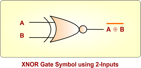
XNOR (Exclusive NOR) logic gate is a digital logic gate that gives the output 1 (HIGH) only when the two inputs are same. If the inputs are the differnet, the output is 0 (LOW). This is the defination for 2-input XNOR gate.
XNOR Logic Gate Notations
The XNOR operation is commonly represented using the ⊙ symbol; all notations are given below
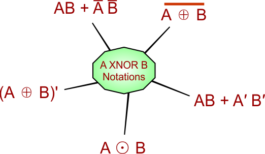
XNOR is the opposite of the XOR gate; when we apply NOT gate to the output of XOR gate, then we get XNOR gate.
XNOR Gate Boolean Expression
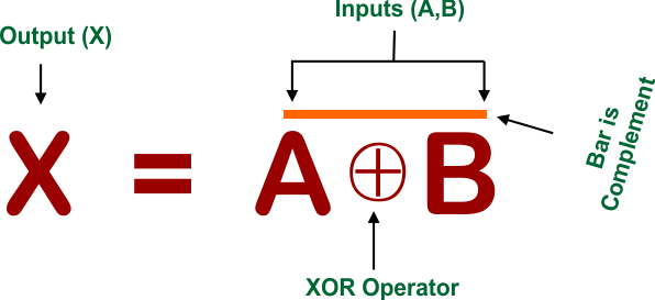
The Boolean expression of XNOR logic Gate is given below
where
A, B are the inputs, X is the output, and ⊕ is the operator for XOR gate, and bar over A and B represents XNOR.
XNOR Gate Symbols
Here are standard diagrams that show the symbol of XNOR logic gate. The number of inputs to a XNOR logic gate can be different according to the requirement
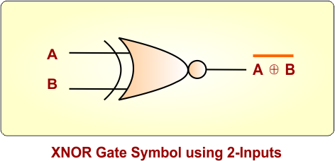
XNOR Gate Symbol for 2 Inputs
In the following XNOR gate diagram, A and B are the inputs, and A⊕B is the output
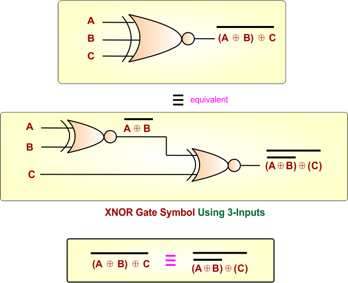
XNOR Gate Symbol for 3 Inputs – Using 3 XNOR
In the following XNOR gate diagram, A, B, and C are the inputs, and A⊕B⊕C with a bar is the output.
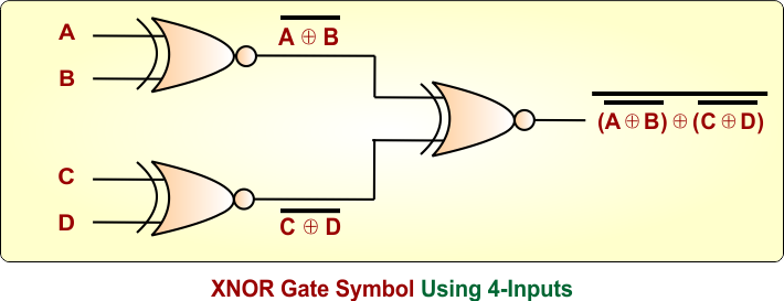
XNOR Gate Symbol for 4 Inputs – Using 3 XNOR
In the following XNOR gate diagram, A, B, C, and D are the inputs, and A⊕B⊕C⊕D with a bar is the output.
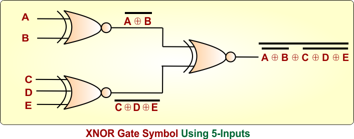
XNOR Gate Symbol for 5 Inputs – Using 3 XNOR
In the following XNOR gate diagram, A, B, C, D, and E are the inputs, and A⊕B⊕C⊕D⊕E with a bar is the output.
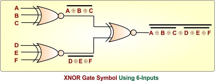
XNOR Gate Symbol for 6 Inputs – Using 3 XNOR
In the following XNOR gate diagram, A, B, C, D, E, and F are the inputs, and A⊕B⊕C⊕D⊕E⊕F with a bar is the output
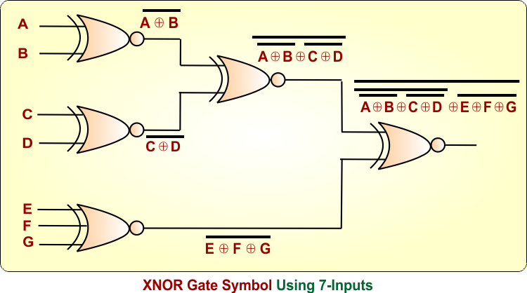
XNOR Gate Symbol for 7 Inputs – Using 5 XNOR
In the following XNOR gate diagram, A, B, C, D, E, F, and G are the inputs, and A⊕B⊕C⊕D⊕E⊕F⊕G with a bar is the output
XNOR Gate Symbol for 7 Inputs – Using 1 XNOR
In the following XNOR gate diagram, A, B, C, D, E, F, and G are the inputs, and A⊕B⊕C⊕D⊕E⊕F⊕G with a bar is the output. In this process, we can use several XNOR gates, but it can be done through a single XNOR gate, as shown in the following diagram.
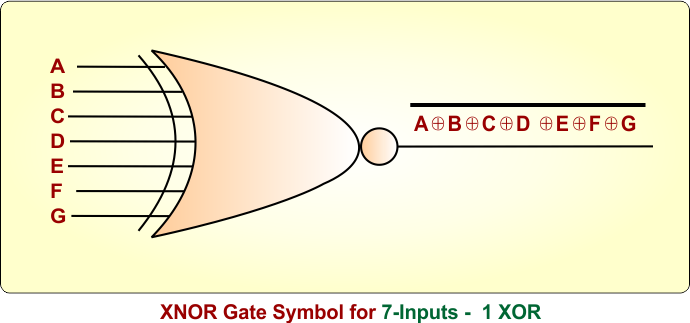
Important: In the above examples
both examples have the same output |
XNOR Logic Gate Truth Table
The truth table shows all possible input combinations and their corresponding outputs for a logic gate. XNOR Logic Gate truth tables for different numbers of inputs are given below
|
The number of possible input combinations in a truth table is calculated using 2ⁿ, where n represents the number of inputs. For Example:
|
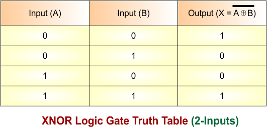
XNOR Logic Gate Truth Table for 2 inputs
A 2-input XNOR gate gives an output of 1 when the two inputs are the same (00 or 11). If the inputs are different (01 or 10), the output is 0. XNOR Logic Gate Truth Table for two inputs (A, B) is given below.
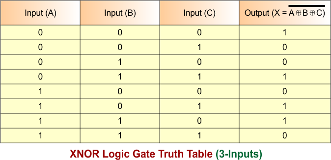
XNOR Logic Gate Truth Table for 3 inputs
A 3-input XNOR gate outputs 1 when an even number of inputs are 1 (0 or 2). If the number of 1s is odd (1 or 3), the output is 0. XNOR Logic Gate Truth Table for three inputs (A, B, C) is given below.
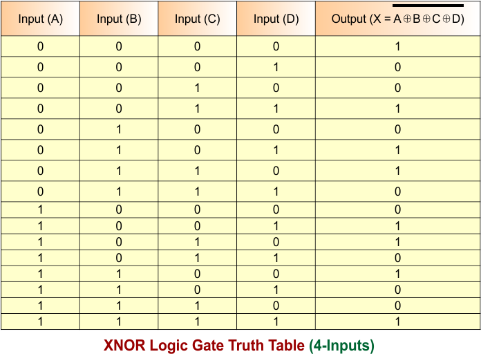
XNOR Logic Gate Truth Table for 4 inputs
A 4-input XNOR gate outputs 1 when an even number of inputs are 1 (0, 2, or 4). If the number of 1s is odd (1 or 3), the output is 0. XNOR Logic Gate Truth Table for four inputs (A, B, C, D) is given below.
Properties of XNOR Gate
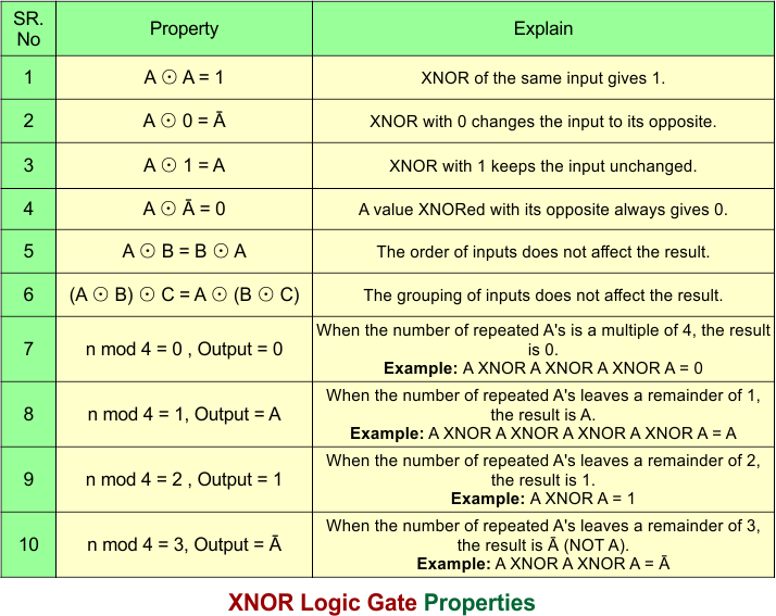
The following diagram shows the main properties of XNOR logic gate
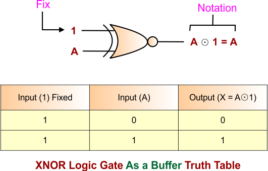
XNOR Gate as Buffer
When a 2-input XNOR logic gate is used, where one input is fixed to 1 and other is “A”. The value of “A” can be either 0 or 1 in binary. It is called a buffer because it produces the output same as input “A” is provided. Notation, Truth table and Symbol of XNOR logic gate as buffer is given below
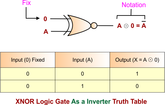
XNOR Gate as Inverter
When a 2-input XNOR logic gate is used, where one input is fixed to 0 and the other is “A”. The value of “A” can be either 0 or 1 in binary. It is called a Inverter becuse it reverse the input value “A”. Notation, Truth table and Symbol of XNOR logic gate as buffer is given below
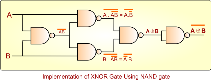
XNOR Gate Using NAND Gate
The following diagram shows how using NAND Logic gates produces the exact output that is produced by a 2-input XNOR Gate. It is done through a NAND Gate
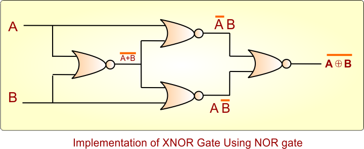
XNOR Gate Using NOR Gate
The following diagram shows how using NOR Logic gates produces the exact output that is produced by a 2-input XNOR Gate. It is done through a NNOR Gate.
XNOR Gate Circuit Diagram Using Transistors
An XNOR Logic Gate can be constructed using transistors; an NPN transistor is mainly used in simple circuit construction. Let’s discuss XNOR Logic Gate circuit using NPN transistors, where two inputs (A, B)
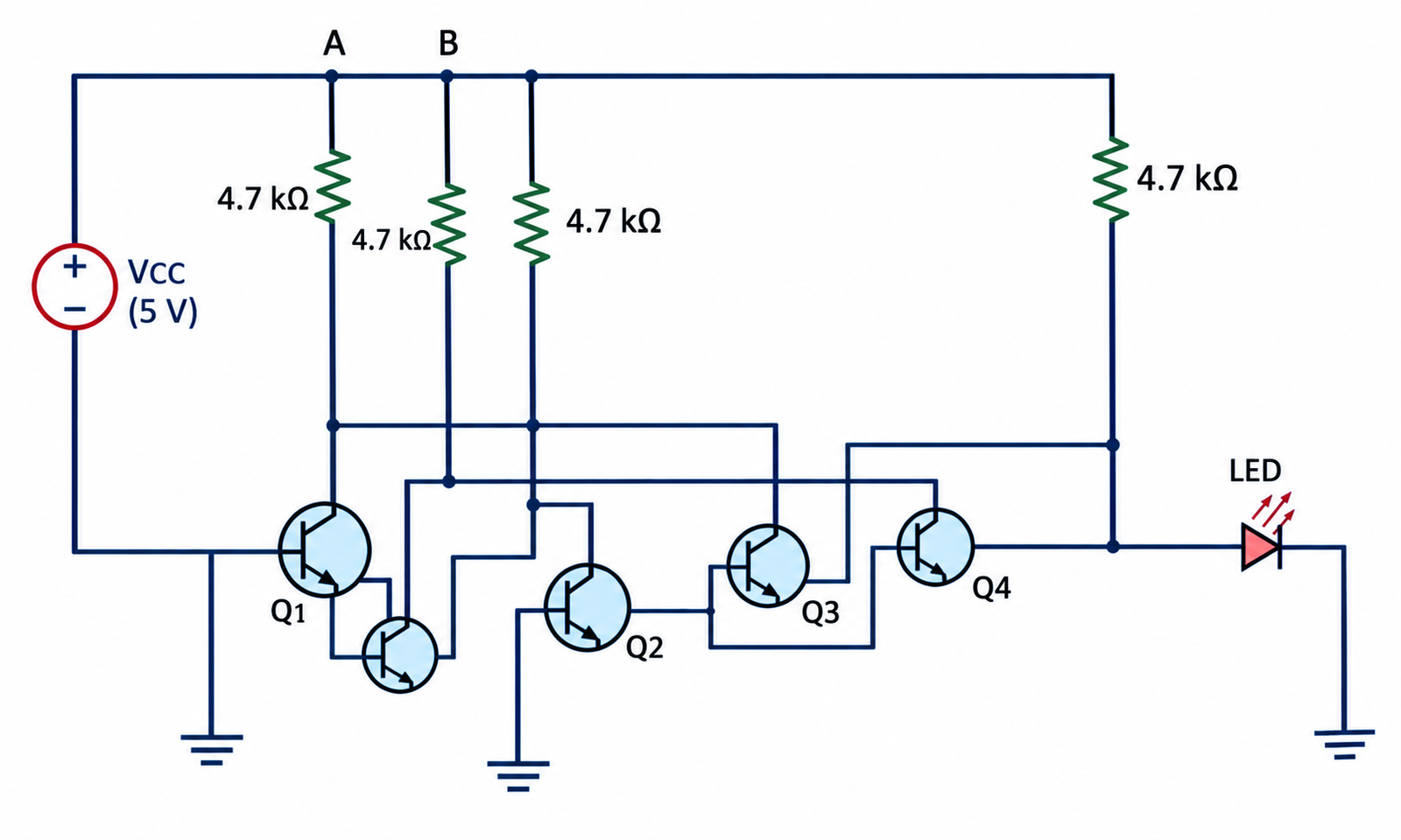
A transistor-based XNOR gate uses NPN transistors as electronic switches to perform the XNOR operation. The output is HIGH (1) when both inputs are the same and LOW (0) when they are different.
| A | B | Output | LED |
|---|---|---|---|
| 0 | 0 | 1 | ON |
| 0 | 1 | 0 | OFF |
| 1 | 0 | 0 | OFF |
| 1 | 1 | 1 | ON |
Circuit Components
- NPN Transistors: Work as electronic switches.
- Inputs A and B: Provide the two binary input signals.
- 4.7 kΩ Resistors: Control and limit the transistor current.
- LED: Shows the output state.
- VCC: Provides power to the circuit.
XNOR Gate Using Switches
The XNOR gate can be represented using two switches (A and B), a battery, and a lamp.
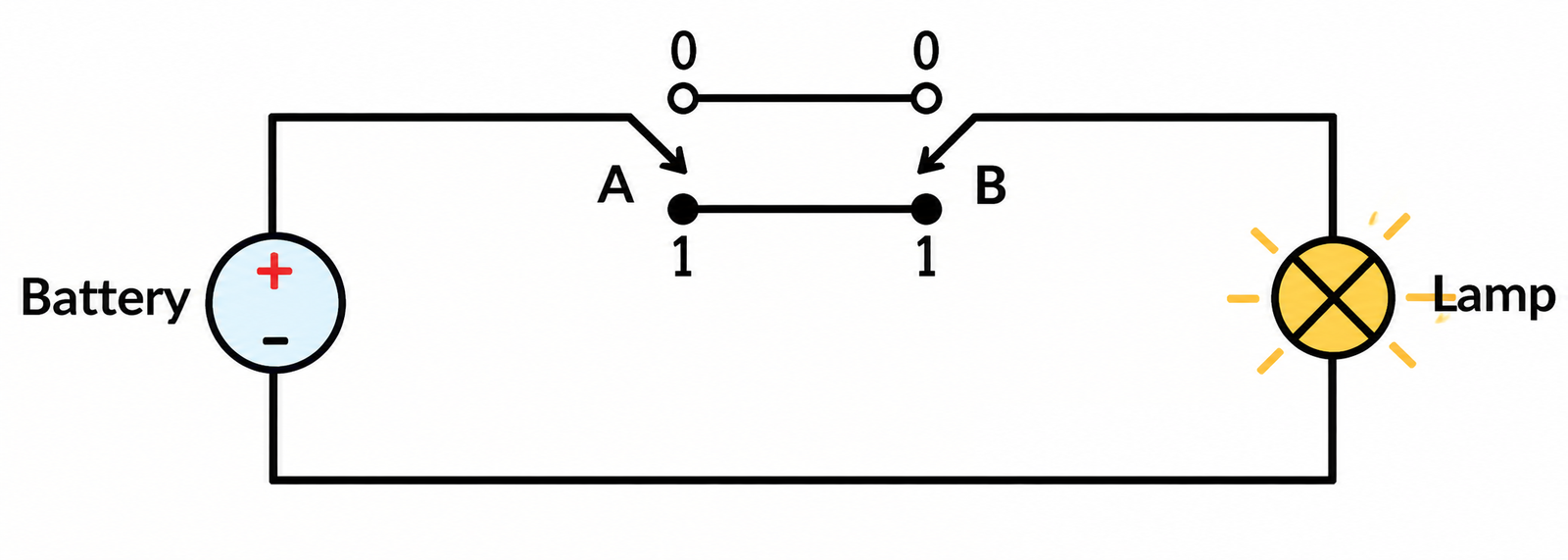
- When A and B are at the same level (00 or 11), the circuit is complete, so the lamp turns ON (1).
- When A and B are at different levels (01 or 10), the circuit is incomplete, so the lamp remains OFF (0).
Therefore, the circuit produces 1 when both inputs are the same and 0 when they are different, which represents the XNOR operation.
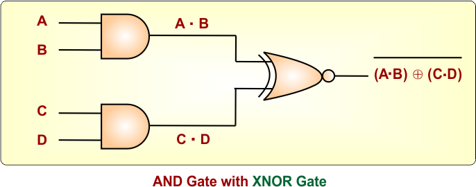
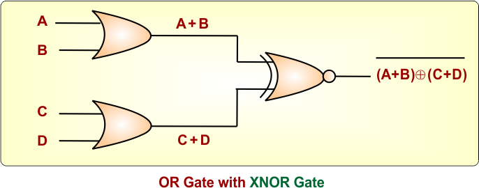
XNOR Logic Gate with OR, AND and NOT Gate
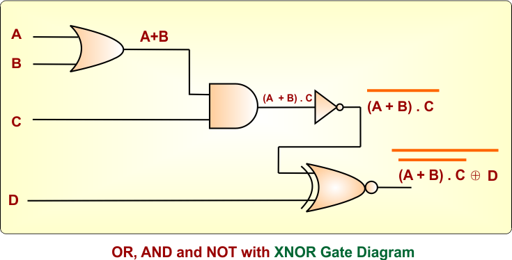
XNOR Logic Gate can be combined with OR, AND, and NOT logic gates to create complex logic functions. The output of one logic gate can be connected to the input of another logic gate to create the required logic.
The following diagram shows the very basic XNOR with OR, AND and NOT logic gates
Applications of XNOR Gate
Here are some common applications of the XNOR Logic Gate:
- Equality Checker: Used to check whether two binary inputs are the same.
- Digital Comparators: Used to compare two binary values.
- Error Detection: Can be used to detect whether transmitted data matches the original data.
- Parity Checking: Used in some digital circuits for checking data bits.
Advantages of XNOR Gate
Here are some advantages of the XNOR Logic Gate:
- Simple comparison: Easily checks whether two inputs are the same.
- Useful in digital circuits: Can be used in many comparison and checking circuits.
- Easy to combine: Can be combined with other logic gates to build larger circuits.
Disadvantages of XNOR Gate
Here are some disadvantages of the XNOR Logic Gate:
- More complex than basic gates: Its circuit is more complex than AND, OR, or NOT gates.
- More components: A transistor-level XNOR circuit may require more components.
- Limited function: It mainly checks whether inputs are equal, so other gates are needed for different operations.