


Logic Gates
The logic gates are an essential part of a digital system. The truth table shows the relationship between the input and output. Each gate has one or two binary input variables and one binary output variable. Binary input/output is in the form of 0 or 1.
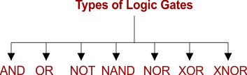
Types of Logic Gates
The seven basic logic gates include AND, OR, NOT, NOR, XOR, NAND, and XNOR. Every logic gate has a different representation and its operation. Let’s explain these logic gates.
1. AND GATE
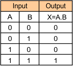
The AND operation only outputs if all its inputs are 1 (ON). It is represented by a dot (.) symbol.
Notation of AND GATE
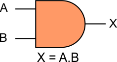
The AND operation has n inputs (n >= 2) and one output. If X is the output and A and B are the inputs, then the Boolean function of AND GATE can be represented in any form of the following,
- X = A AND B
- X = A.B
- X = AB
Diagram of the AND GATE
The Truth Table of AND GATE
2. OR GATE
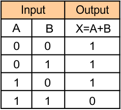
The OR operation only gives output if one or more inputs are 1 (ON). It is represented by a Plus (+) symbol.
Notation of OR GATE
There are n inputs (n >= 2) and one output in the OR operation. If X is the output and A and B are the inputs, then the Boolean function of OR Gate can be represented in any form of the following,
- X = A OR B
- X = A + B
Diagram Of OR GATE

Truth Table Of OR GATE
3. NOT GATE
The NOT gate provides an inverted output of its input. i.e., if the input is 1, then the output will be 0 and vice versa. It is also known as an Inverter.
Notation of NOT GATE
If X is the output and A is the input, then the Boleyn function can be represented in any form of the following,
- X = A-Bar
- X = NOT A
- X= A’
Diagram Of NOT GATE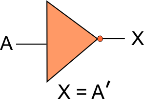
Truth Table Of NOT GATE

4. NAND GATE
The NAND (NOT-AND) gate equals the combination of the AND and NOT gates. NAND gate gives output (1) if any of the inputs are 0. The NAND gate is symbolically represented as an AND gate with a small circle on the output. Notation of this small circle shows the inversion.
Notation of NAND GATE
The NAND operation has n inputs (n >= 2) and one output. If X is the output and A and B are the inputs, then the Boleyn function can be represented in any form of the following,
- X = (A AND B)’
- X = (A.B)’
- X = (AB)’
- X = (A.B)-Bar
Diagram of NAND GATE

Truth Table of NAND GATE

5. NOR GATE
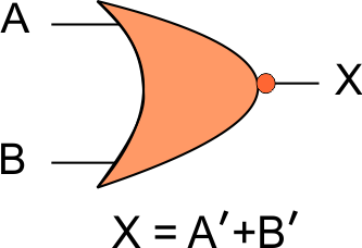
NOR (NOT-OR) gate equals the combination of OR gate and NOT gate. It gives a 0 output if any of the inputs are 1. It is symbolically represented as an OR gate with a small circle on the output. Notation of this small circle shows the inversion.
Notation of NAND GATE
The NAND operation has n inputs (n >= 2) and one output. If X is the output and A, and B are the inputs, then the Boleyn function can be represented in any form of the following,
- X = (A OR B)’
- X = (A+B)’
- X = A+B(BAR)
Diagram of NOR GATE
Truth Table of NOR GATE

6. Exclusive-OR/ XOR GATE
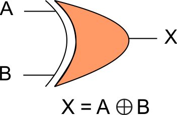
The XOR (‘Exclusive-OR’) gate gives an output (0) if both inputs are the same, i.e., A=0 and B=0. The XOR operation is denoted by an encircled plus sign ⊕. The small, narrow line at the input side represents exclusivity.
Notation of XOR GATE
Boolean function of XOR can be represented in any form of the following,
- X = A ⊕ B
- X = A’B+AB’
Diagram of XOR GATE
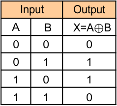
Truth Table of XOR GATE
7. Exclusive-NOR (X-NOR) GATE
The Exclusive-NOR gate applies the inversion operation on the XOR gate. It will give an output (1) if both inputs are the same, i.e., A=0 and B=0. The small, narrow line at the input side represents exclusivity. A small circle at the output shows the inversion.
Notation Of X-NOR Gate
Boolean functions of Exclusive-NOR can be represented in any form of the following,
- X = (A ⊕ B)’
- X = A’B’+AB
Diagram of Exclusive-NOR

Truth Table of Exclusive-NOR GATE

Combination Of Various Logic Gates

We can use various gates together to get the desired output, i.e., “OR gate” and Two “AND Gates,” as shown in the following diagram.
The truth table of the above diagram, is given below.
