


Computer Instructions
Computer instructions are a set of machine language instructions that a particular processor understands and executes. A computer performs tasks according to the instructions provided.
Fields of Computer instructions
There are three basic fields of each instruction in a computer. Let’s look at the following diagram of the 16-bit instruction 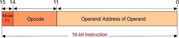 I. The Operand is a data. But the operand field may contain actual data or the address of that data. Address of data means the location of the register or memory where actual data is present. II. The Opcode field tells the operation which will be performed on data, i.e., +, -, x, <, etc. III. The Mode field tells about the addressing modes. It is a source to find the operand. It tells whether the operand field contains the actual data or address of memory, address of the register, or address of address, etc. i.e. if Mode bit = 0 then it is direct addressing and if Mode bit =1 then it is an indirect addressing mode. We will cover all of this in detail in addressing modes.
Types of Computer Instructions
There are three types of a basic computer. The computer instruction formats based on memory references are listed below
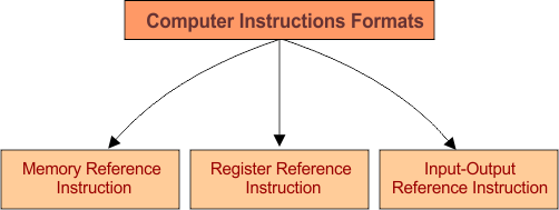
1. Memory Reference Instruction
The instruction format of memory reference instructions is 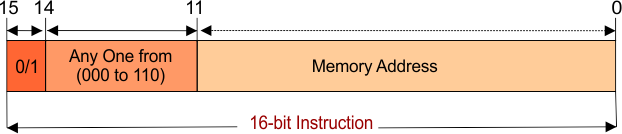
- Where the 15th bit, which is “I”. This value of “I” will be 0 to represent direct addressing mode or 1 to represent indirect addressing mode.
- 12 to 14 bits represent the Opcode value. The opcode value will be between 000 to 110. These 7 values (000 to 110) represent the 7 decode operations. Decode operations represented by D0 to D6 as shown in the following diagram.
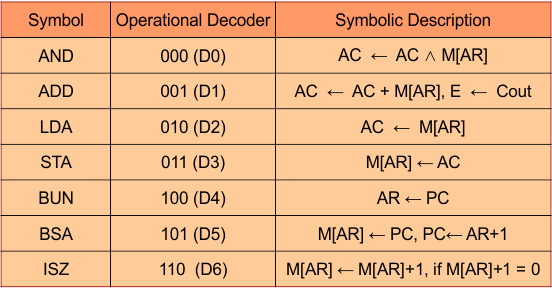 When the value of Opcode = 001 (D1), then the ADD operation will be performed on the operand.
- 0 to 11 bits represent the address of the memory location or operand itself.
2. Register – Reference Instruction
The instruction format of memory reference instructions is 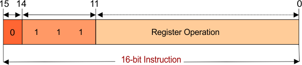
- The 15th bit, which is I, will always be equal to 0 to represent the register addressing mode.
- 12 to 14 bits represent the Opcode value. The opcode value will always equal to 111.
- 0 to 11 bits of operand represents the register operation. Different operations can be performed on the register by setting the value 1 of any location from 0 to 11 bits. So, 12 operations can be performed on registers by setting 1 to different locations (B0 to B11).
For example, when the value of operand = 000000000001, then the HLT operation will perform on the register. As shown in the following table 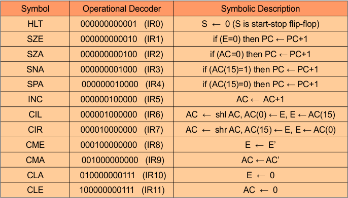
3. Input-Output Instruction
The instruction format of memory reference instructions is 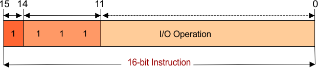
- The 15th bit, which is I, will always be equal to 1 to represent the I/O addressing mode.
- 12 to 14 bits represent the Opcode value. The opcode value will always equal to 111.
- 0 to 5 bits of operand will always be zero, and 6-11 bits represent the I/O operation. Different operations can be performed on I/O by setting the value 1 of any location from 6 to 11 bits. So, 6 operations can be performed on I/O by setting 1 to different locations (B6 to B11).
For example, when the value of operand = 000001000000, then the IOF operation will perform on the register. As shown in the following table 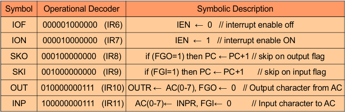
Basic Categories Of Computer Instructions
There are 3 basic categories of instruction in General Computers
Note that the above-discussed instructions are not specified for a specific CPU. Intel, AMD, etc., but these instructions are common in all processors.