


Design of Control Unit
The Control Unit (CU) generates timing and control signals to perform different operations in the computer system. It also communicates with ALU and RAM.
Control units can be designed in two ways, which are explained below,
1. Hardwired Control Unit
The basic components of hardwired control units are
- 2 decoders, one is 3×8, and the other is 4×16.
- One sequential counter
- One control logic gate
- and one Instruction Register
The block diagram of a Hardwired Control organization is shown below,
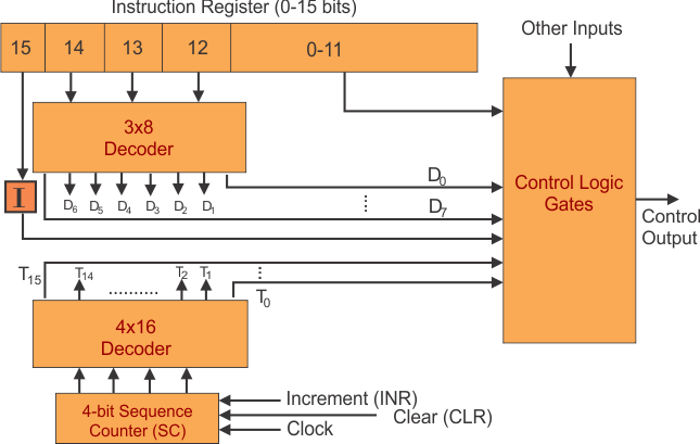
- As the above diagram shows,
- A Hardwired Control contains two decoders, one Instruction Register, one sequence counter, and control logic gates.
- Fetched instructions from the memory are placed in the instruction register (IR).
- An instruction register contains three fields: Operand (0-11 bits), Opcode (12-14 bits), and Mode (15 bits).
- The operand provides the operand or address of the operand and is directly connected with control logic gates.
- The operation code (Opcode) bits are connected with a 3 x 8 decoder. The outputs of the decoder are denoted by the symbols D0 through D7.
- Mode Bit 15 represents the addressing modes and is directly connected with control logic gates.
- The Sequence counter (SC) can count from 0 through 15 in binary and is connected with a 4×16 decoder.
Let’s Explain with an Example
If the input register contains the value 1001010001010111, then we can understand this instruction by understanding the values of its fields.
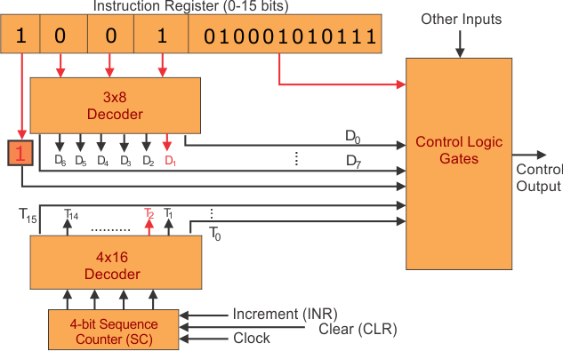
- As the 15th bit is 1. So, it represents an indirect addressing mode.
- 12,13,14 bits of opcode are 001, which represents ADD operation. D1 also denotes the ADD operation.
- 0 to 11 bits are 010001010111, which represents the address of the operand.
- Suppose this instruction is executed at Time T2. Then, it can symbolically represent D1T2, and SC becomes zero.
- This instruction means that the ADD operation is applied to the address (010001010111) of memory.
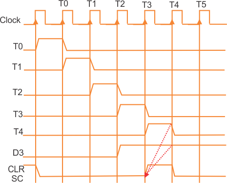
Timing cycle
Let’s explain the time cycle at point D3T4: SC←0
Disadvantages
- Increasing the control unit’s size complicates the control unit’s organization.
- If a bit of change or modification is required in control units, then it causes the modification of the entire control unit, which is problematic.
2. Micro-Programmed Control
The micro-programmed control organization is implemented using the programming technique. Micro-programs consist of micro-instructions. A Block diagram of the Micro-programmed Control organization is shown below.
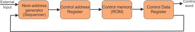
- The Control address register (CAR) specifies the address of the micro-instruction. So, the address of the micro-instruction that is to be executed is stored in the CAR (Control Address Register)
- ROM is permanent storage that stores the value of the control address register.
- The control data register holds the microinstruction fetched from the memory (ROM).
- Micro-instruction corresponding to the address (stored in CAR) is fetched from control memory and stored in the control data register (CDR)
- This microinstruction contains a control word to execute one or more micro-operations for the data processor.
- Micro-programs contain micro-instructions, and micro-instructions contain micro-operations. When the execution of all micro-operations of micro-instruction is completed. Then, the address of the next micro-instruction is pointed. The next address generator is a micro-program sequencer.
Advantages
- It is less complex to design because micro-programs are implemented using software routines.
- It is more flexible because design modification, correction, and enhancement are straightforward.
- Errors can easily be removed.
Disadvantages
- This Technology is slower than the hardwired control unit because the time required to access the micro-instructions from control memory is larger.
- It is more expensive than hardwired due to the use of ROM.
- Required more Chip area as compared to hardwire
Difference between Hardwired Control and Micro programmed Control
| Hardwired Control | Micro programmed Control |
| This Technology is circuit-based. | This Technology is software-based. |
| It is implemented through flip-flops, gates, decoders, etc. | Micro-instructions generate signals, and then these signals control the execution of instructions. |
| All the Instructions are register-based. | Instructions are not register-based. |
| ROM is not used in this Technology. | ROM is used in this Technology. |
| This is used in RISC. | This is used in CISC. |
| Difficult to modify. | Easily modified. |
| Fixed instruction format. | Variable instruction format (16, 32,64 bits per instruction). |
| The chip area is less. | The chip area is large. |