












OR Logic Gate
The OR logic gate is a basic logic gate that gives an output of 1 (High) when at least one input is “1”. It gives only the output 0 (Low) when all inputs are “0”
OR Gate Boolean Expression
The Boolean expression of OR logic Gate is given below
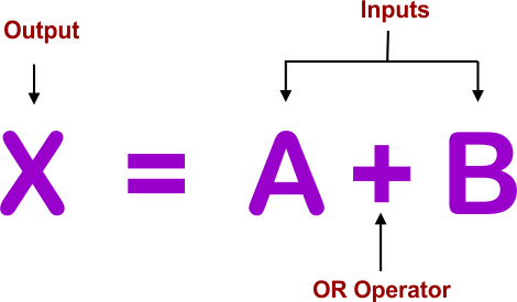
where
A, B are the inputs, X is the output, and + is the operator for OR Gate
OR Gate Symbols
Here are standard diagrams that show the symbol of OR logic gate. The number of inputs to a OR logic gate can be different according to the requirement
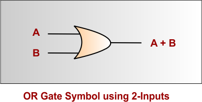
OR Gate Symbol for 2 Inputs
In the following OR gate diagram, A and B are the inputs, and A+B is the output
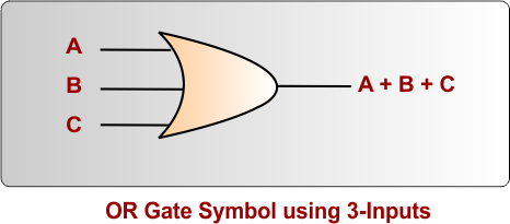
OR Gate Symbol for 3 Inputs
In the following OR gate diagram, A, B, and C are the inputs, and A+B+C is the output
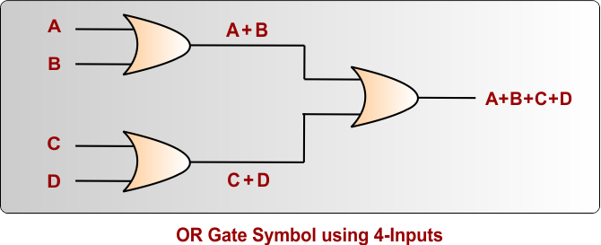
OR Gate Symbol for 4 Inputs
In the following OR gate diagram, A, B, C, and D are the inputs, and A+B+C+D is the output
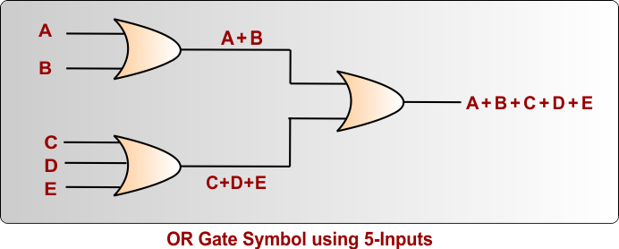
OR Gate Symbol for 5 Inputs
In the following OR gate diagram, A, B, C, D, and E are the inputs, and A+B+C+D+E is the output
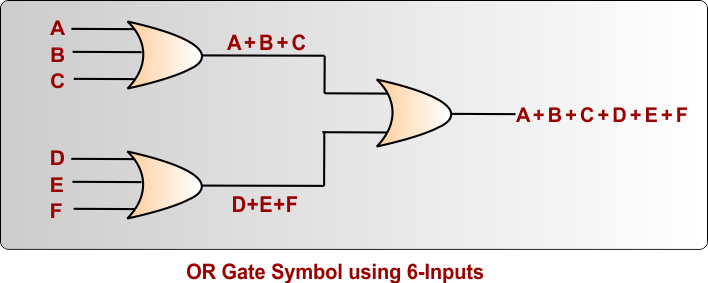
OR Gate Symbol for 6 Inputs
In the following OR gate diagram, A, B, C, D, E, and F are the inputs, and A+B+C+D+E+F is the output
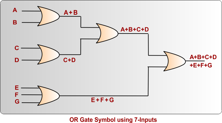
OR Gate Symbol for 7 Inputs
In the following OR gate diagram, A, B, C, D, E, F, and G are the inputs, and A+B+C+D+E+F + G is the output
OR Gate Equivalent Circuit
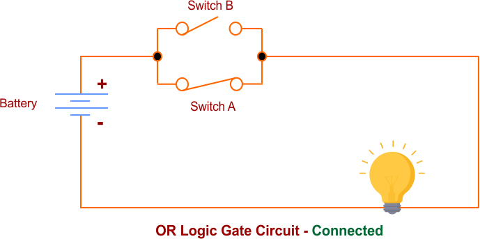
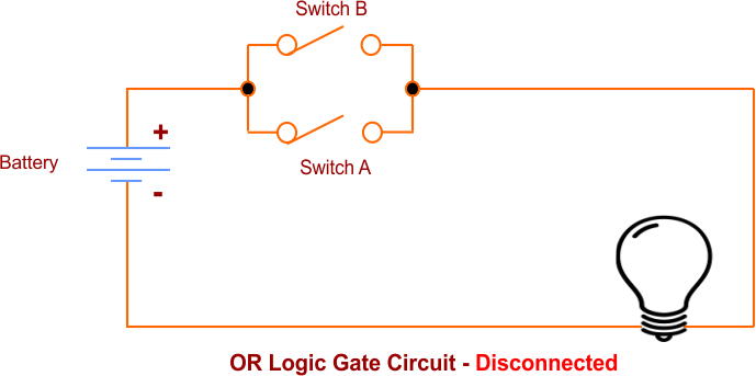
OR Logic Gate can also be represented using an electrical circuit. In this circuit, two switches are connected in parallel.
Case 01: If either one or both switches are connected (closed), the lamp will light up as shown in the following OR Logic gate diagram
Case 02: The lamp remains OFF only when both switches are open (unconnected), as shown in the following OR Logic gate diagram
OR Logic Gate Truth Table
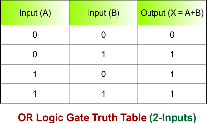
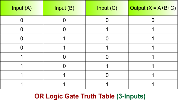
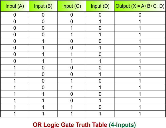
Truth table shows all possible input combinations and their corresponding outputs for a logic gate. OR Logic Gate truth tables for different numbers of inputs are given below
|
The number of possible input combinations in a truth table is calculated using 2ⁿ, where n represents the number of inputs. For example:
|
OR Logic Gate Truth Table for 2 inputs
OR Logic Gate Truth Table for two inputs (A, B) is given below
OR Logic Gate Truth Table for 3 inputs
OR Logic Gate Truth Table for three inputs (A, B, C) is given below
OR Logic Gate Truth Table for 4 inputs
OR Logic Gate Truth Table for four inputs (A, B, C, D) is given below
OR Gate Circuit Diagram Using Transistors
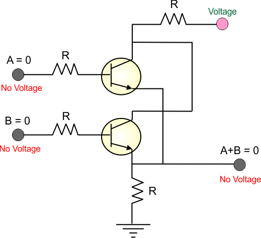
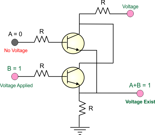
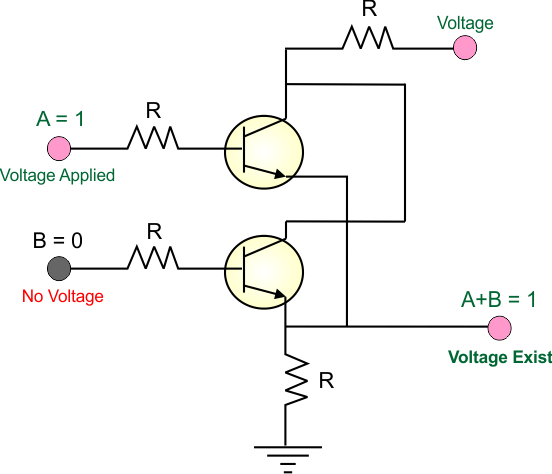
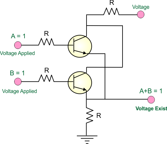
An OR Logic Gate can be constructed using transistors; an NPN transistor is mainly used in simple circuit construction. This NPN circuit uses two inputs; if either input is High (1), it produces an output (1), which is the basic principle of an OR logic gate.
|
Very Important: In NPN transistrr, If voltage is applied at the collector but no voltage is present at base side, then transistor will remain OFF.
|
Let’s discuss OR Logic Gate circuit using NPN transistors, where two inputs (A, B)
Case 01: When A = 0, B = 0, then no current is applied to either transistor’s base, so both transistors remain OFF, and the output is 0.
Case 02: When A = 0, B = 1, then no current is applied to the base of transistor B, turning it ON and producing an output of 1.
Case 03: When A = 1, B = 0, then current is applied to the base of transistor A, turning it ON, so the output is 1.
Case 04: When A = 1, B = 1, then current is applied to the bases of both transistors, turning both ON, and the output remains 1.
Applications of OR Gate
Here are some applications of the OR Logic Gate
1. Automatic Watering System
An OR Logic gate can be used in an automatic watering system. If any sensor detects that water is needed, the OR Logic gate produces a high output (1), which can turn ON the watering system.
2. Home Automation
OR Logic gates are useful in home automation systems. They can combine signals from different sensors or switches. For example, if the temperature in any room becomes too high or too low, the system can turn on the cooling or heating system.
3. Emergency Lighting
OR gates can be used in emergency lighting systems. If any emergency switch or sensor sends a high signal, the OR gate produces a high output and turns on the emergency lights.
4. Security Systems
In security systems, multiple sensors can be connected to an OR gate. If any sensor detects motion, an open door, or another security event, the output becomes high and can activate an alarm.
5. Alarm Systems
OR gates can be used in fire or warning systems. If any connected detector or sensor sends a signal, the OR gate can activate the alarm.
Advantages of OR Gate
Here are some Advantages of OR Logic Gate
1. Simple Design
OR gates are simple logic gates that are easy to understand, design, and use in digital circuits.
2. Multiple Inputs
An OR gate can work with two or more inputs. This makes it useful when a system needs to respond to any one of several conditions.
3. Flexible
Because it can combine multiple input signals into one output, an OR gate can be used in many different digital and electronic systems.
4. Important Building Block
OR gates are one of the basic building blocks of digital electronics. They are used with other gates to create more complex circuits and logical functions.
5. Fast Operation
OR gates can quickly produce an output when the input changes, making them useful in digital systems that require fast decision-making.
Disadvantages of OR Gate
Here are some disadvantages of OR Logic Gate
1. Limited Information
If the output is high (1), we only know that at least one input is high. We cannot determine which specific input caused the output without checking the inputs separately.
2. Only Binary Output
An OR gate produces only two output values: 0 or 1. Therefore, it may not be suitable for systems that require more detailed information.
3. Cannot Identify Individual Inputs
When multiple inputs are connected, the OR gate combines them into one output. This makes it difficult to identify the exact source of a high signal.
4. More Inputs Can Increase Circuit Complexity
Using OR gates with many inputs may require additional hardware or more complex circuit designs.
5. Cannot Perform All Logical Operations Alone
An OR gate performs only the OR operation. More complex logical functions usually require combining it with other gates, such as NOT, AND, NAND, or NOR gates.