











NOR Logic Gate
When we combine OR logic gate with NOT logic gate, we get NOR logic gate. It means OR + NOT = NOR. First, we get the output of OR logic gate and then apply the NOT gate, which generates NOR logic gate.
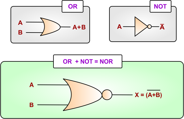
- NOR logic gate generates output 1 (HIGH) when all inputs are 0 (LOW).
- NOR logic gate generates output 0 (LOW) when atleast one input is 1 (HIGH).
Keep in mind, OR and NOR are opposite in terms of output.
NOR Logic Gate Boolean Expression
The Boolean expression of NOR logic Gate is given below
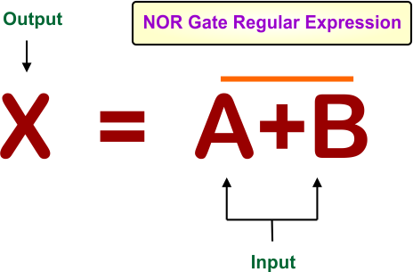
where
- A, B are the inputs variables
- X is the output variable
- + is the operator for OR Gate
- bar (-) represents the NOT operation.
NOR Logic Gate Symbols
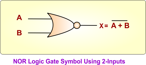
Here are standard diagrams that show the symbol of NOR logic gate. The number of inputs to a NOR logic gate can be different according to the requirement
NOR Logic Gate Symbol for 2 Inputs
In the following NOR gate diagram, A and B are two inputs, and X is the output
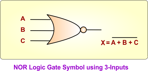
NOR Gate Symbol for 3 Inputs
In the following NOR gate diagram, A, B, and C are the inputs, and X is the output
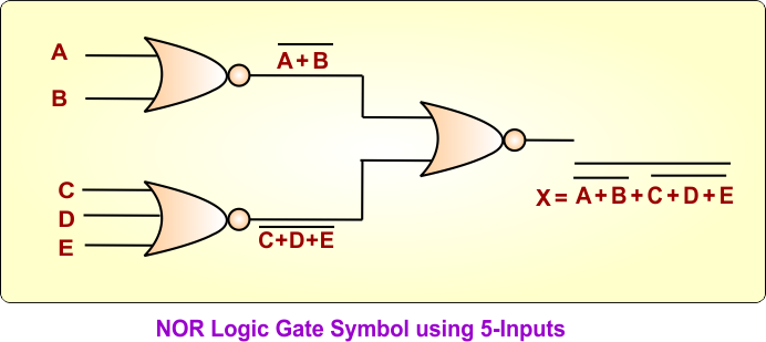
NOR Logic Gate Symbol for 5 Inputs using 3 NOR
In the following NOR gate diagram, A, B, C, D, and E are the inputs, and X is the output
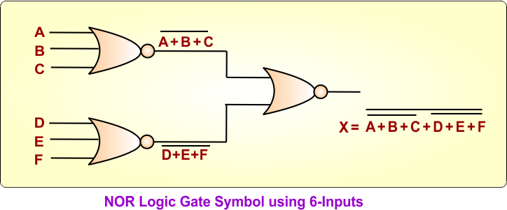
NOR Gate Symbol for 6 Inputs using using 3 NOR
In the following NOR gate diagram, A, B, C, D, E, and F are the inputs, and X is the output
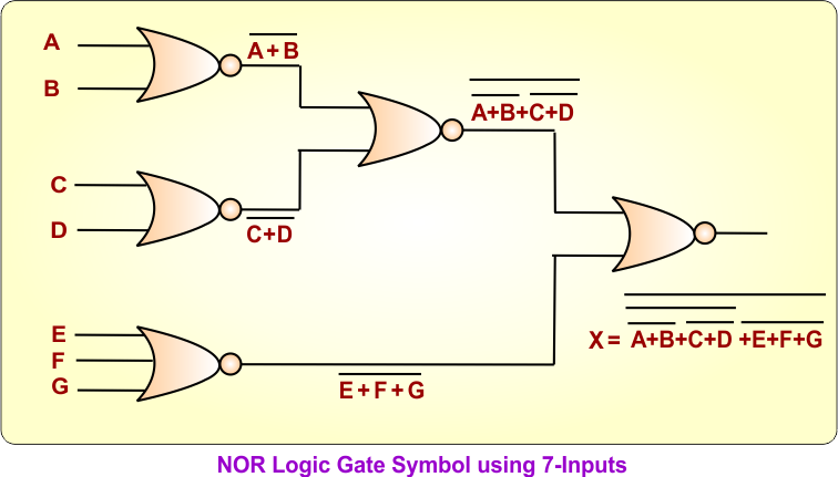
NOR Gate Symbol for 7 Inputs using 5 NOR
In the following NOR gate diagram, A, B, C, D, E, F, and G are the inputs, and X is the output
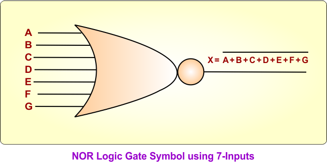
NOR Gate Symbol for 7 Inputs using 1 NOR
In the following NOR gate diagram, A, B, C, D, E, F, and G are the inputs, and X is the output
NOR Logic Gate Equivalent Circuit
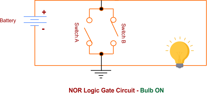
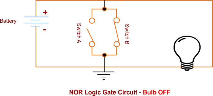
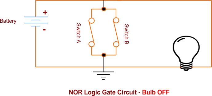
NOR logic gate with two switches A and B with lamp for output is given below
Case 01: When A = 0 and B= 0, Lamp will ON because NOR output is 1.
Case 02: When A = 0 and B= 1, Lamp will OFF because NOR output is 0.
Case 03: When A = 1 and B= 0, Lamp will OFF because NOR output is 0.
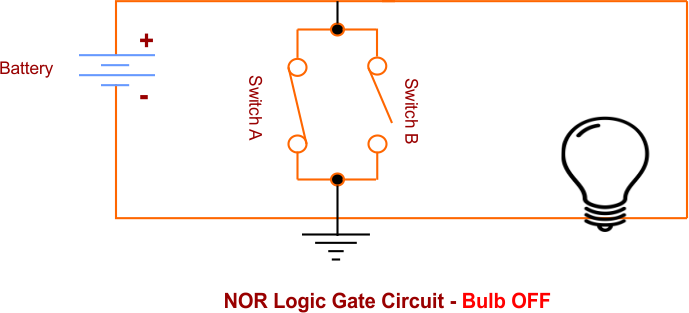
Case: 04: When A = 1 and B= 1, Lamp will OFF because NOR output is 0.
NOR Gate in Terms of Transistor
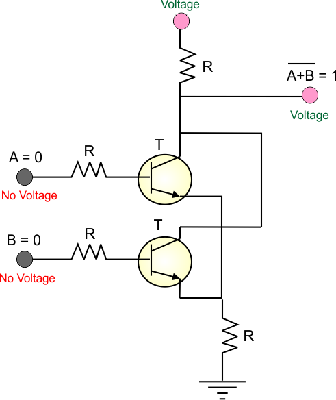
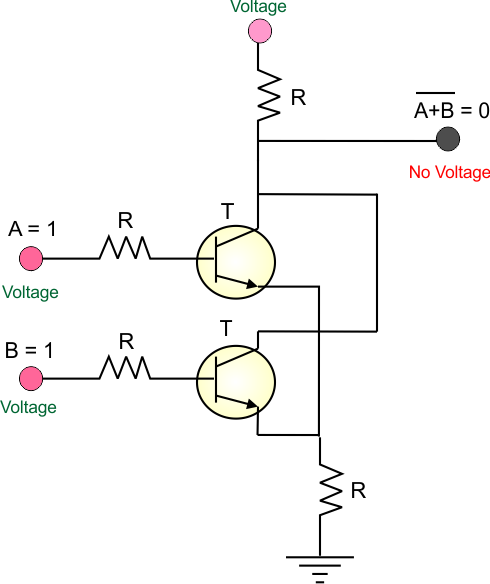
A transistor-based NOR gate uses two or more NPN transistors connected in parallel. The output becomes HIGH (1) only when all transistors are OFF. If any transistor turns ON, it pulls the output LOW (0).
Case 01: When A = 0 and B= 0, Transister contains no base current; the NOR output is 1 because of the direct voltage applied.
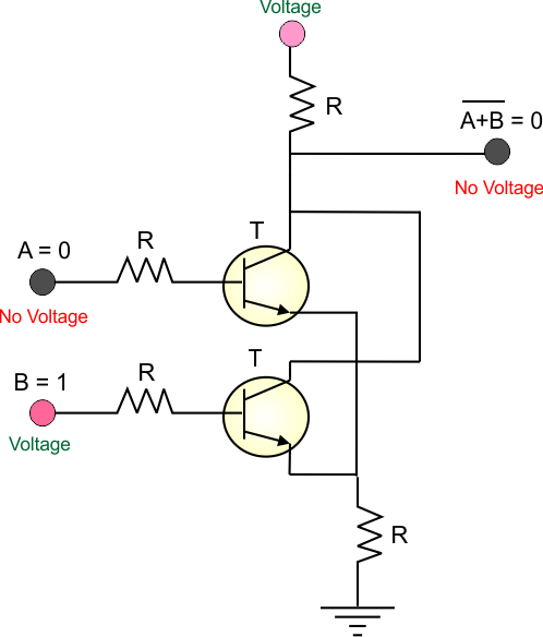
Case 02: When A = 0 and B= 1, Transister B contains current at base, which will pass to ground (in the diagram) instead of the output. So, output = 0
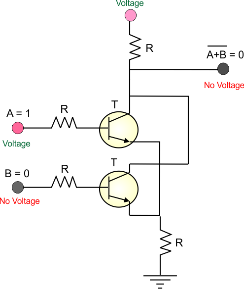
Case 03: When A =1 and B= 0, Transister A contains current at base, which will pass to ground (in the diagram) instead of the output. So, output = 0
Case 04: When A =1 and B= 1, Transister A and B contains current at base, which will pass to ground (in the diagram) instead of the output. So, output = 0
NOTE:
- Vcc and pull-up resistor: Vcc is connected to the output through a pull-up resistor to maintain a HIGH output when the transistors are OFF.
- Collectors: The collectors of T1 and T2 are connected together at the output.
- Emitters: The emitters of both transistors are connected to ground (0V).
- Inputs: Input A is connected to the base of T1, while input B is connected to the base of T2.
NOR Logic Gate Truth Table
The truth table represent all possible input combinations and their corresponding outputs for any logic gate. NOR Logic Gate truth tables for different numbers of inputs are given below
|
The total number of possible input combinations in a truth table is calculated through 2ⁿ formula, where n represents the number of inputs. For example:
|
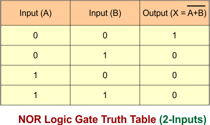
NOR Logic Gate Truth Table for 2 inputs
NOR Logic Gate Truth Table for two inputs (A, B) is given below
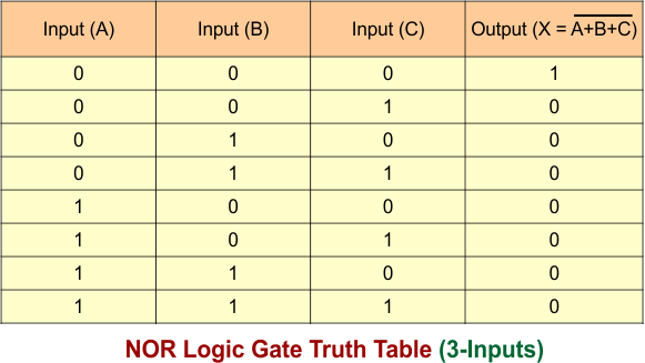
NOR Logic Gate Truth Table for 3 inputs
NOR Logic Gate Truth Table for three inputs (A, B, C) is given below
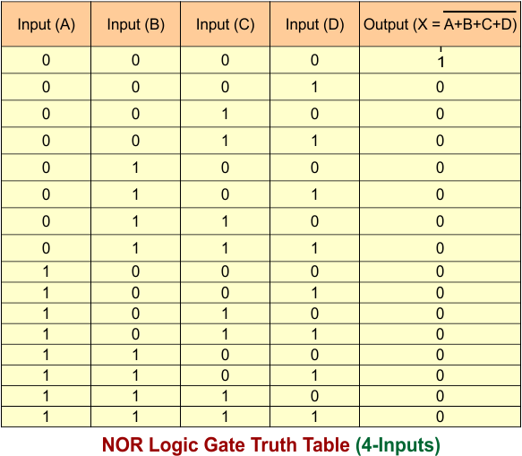
NOR Logic Gate Truth Table for 4 inputs
NOR Logic Gate Truth Table for four inputs (A, B, C, D) is given below
NOR Gate as a Universal Gate
A NOR gate is called a universal gate because it can be used to implement all the basic logic gates, such as NOT, OR, and AND. By combining NOR gates in different ways, other gates such as NAND, XOR, and XNOR can also be constructed.
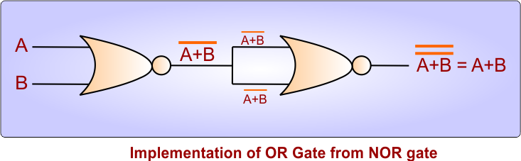
OR Gate Using NOR Gates
The following diagram of using NOR Logic gates produce the exact output which is produced by a 2-input OR Gate. It is done through NOR Gate.
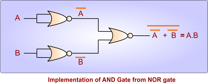
AND Gate Using NOR Gates
The following diagram of using NOR Logic gates produce the exact output which is produced by a 2-input AND Gate. It is done through NOR Gate.
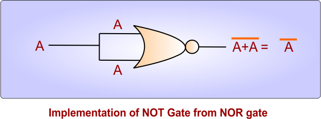
NOT Gate Using NOR Gates
The following diagram of using NOR Logic gates produce the exact output which is produced by a NOT Gate. It is done through NOR Gate.
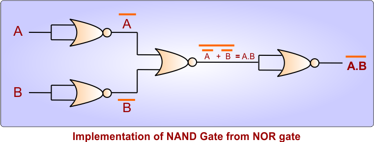
NAND Gate Using NOR Gates
The following diagram of using NOR Logic gates produce the exact output which is produced by a 2-inputs NAND Gate. It is done through NOR Gate.
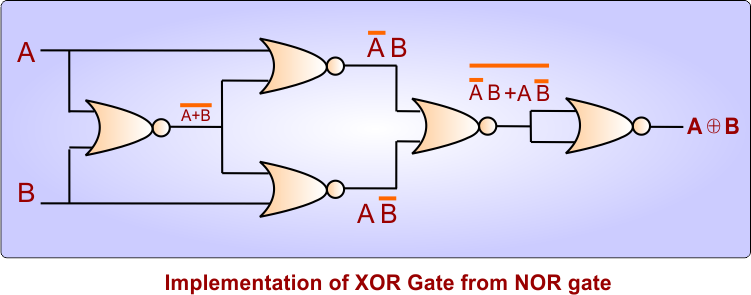
XOR Gate Using NOR Gates
The following diagram of using NOR Logic gates produce the exact output which is produced by a 2-inputs XOR Gate. It is done through NOR Gate.
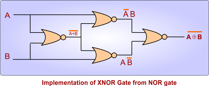
XNOR Gate Using NOR Gates
The following diagram of using NOR Logic gates produce the exact output which is produced by a 2-inputs XNOR Gate. It is done through NOR Gate.