












Commutative Law in Boolean Algebra
According to the Commutative Law in Boolean Algebra, changing the order of Boolean variables does not change the result of an operation. The Commutative Law applies to both AND and OR operations.
- In the AND operation, the order of variables can be changed without changing the result.
- In the OR operation, the order of variables can be changed without changing the result.
Commutative laws are fundamental laws used to simplify Boolean expressions and understand the behavior of digital logic circuits.
Types of Commutative Laws
There are two types of Commutative Laws in Boolean algebra:
1. AND Commutative Law
The Commutative Law for the AND operation states that changing the order of the variables does not change the result. It can be expressed as: A · B = B · A. The following diagram of the AND Commutative Law explains it.
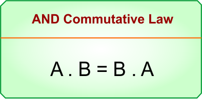
Let’s explain the diagram.
A · B = B · A. It means that changing the order of A and B does not change the output.
- If A = 0 and B = 1, then 0 · 1 = 0 and 1 · 0 = 0
- If A = 1 and B = 1, then 1 · 1 = 1 and 1 · 1 = 1
Therefore, A · B = B · A because the output remains the same when the positions of A and B are exchanged. It is called the AND Commutative Law.
2. OR Commutative Law
The Commutative Law for the OR operation states that changing the order of the variables does not change the result. It can be expressed as: A + B = B + A. The following diagram of the OR Commutative Law explains it.
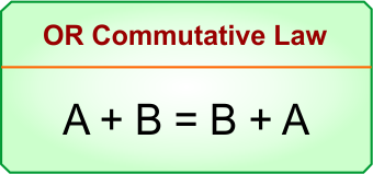
Let’s explain the diagram.
A + B = B + A. It means that changing the order of A and B does not change the output.
- If A = 0 and B = 1, then 0 + 1 = 1 and 1 + 0 = 1
- If A = 1 and B = 1, then 1 + 1 = 1 and 1 + 1 = 1
Therefore, A + B = B + A because the output remains the same when the positions of A and B are exchanged. It is called the OR Commutative Law.
Commutative Law Truth Table
Let’s explain the truth table of AND and OR operations in Boolean algebra.
AND Commutative Law Truth Table
In an AND operation, changing the order of A and B does not change the output. The following diagram shows the truth table of the AND Commutative Law.
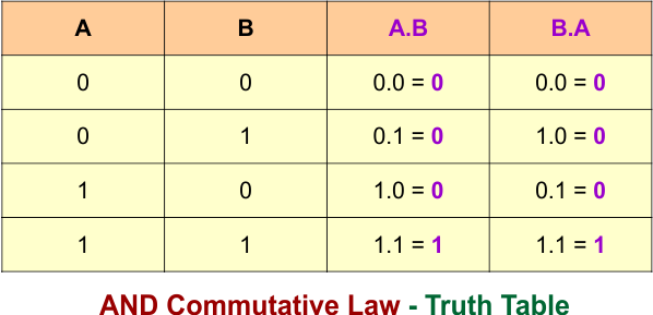
So, A · B = B · A because both expressions produce the same output for every combination of A and B.
OR Commutative Law Truth Table
In an OR operation, changing the order of A and B does not change the output. The following diagram shows the truth table of the OR Commutative Law.
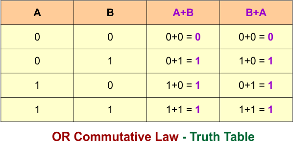
So, A + B = B + A because both expressions produce the same output for every combination of A and B.
Commutative Law Logic Gates
Let’s explain the logic gates of the Commutative Law in Boolean algebra.
AND Commutative Law – Logic Gate
In the AND operation, the inputs can be interchanged without changing the output. The following diagram shows the AND Commutative Law using logic gates.
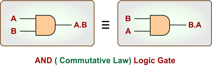
The first AND gate represents A · B, while the second AND gate represents B · A. Both gates produce the same output.
OR Commutative Law – Logic Gate
In the OR operation, the inputs can be interchanged without changing the output. The following diagram shows the OR Commutative Law using logic gates.
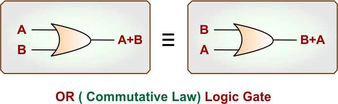
The first OR gate represents A + B, while the second OR gate represents B + A. Both gates produce the same output.
Commutative Law – Circuit Switches
Let’s explain the Commutative Law using circuit switches. The Commutative Law can be represented using circuit switches to show that changing the order of the switches does not change the final output.
AND Commutative Law – Circuit Switches
In a series circuit, both switches must be closed for the output to be 1. Changing the order of the switches does not change the result, giving A · B = B · A.
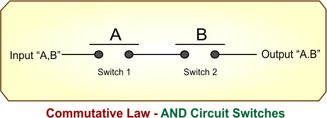
In the first circuit, switch A comes before switch B. In the second circuit, switch B comes before switch A. Both circuits produce the same output.
- Case 01: When A = 0 and B = 0, the output is 0.
- Case 02: When A = 0 and B = 1, the output is 0.
- Case 03: When A = 1 and B = 0, the output is 0.
- Case 04: When A = 1 and B = 1, the output is 1.
Therefore, changing the order of the switches does not change the output.
OR Commutative Law – Circuit Switches
In a parallel circuit, the output is 1 when either switch is closed. Changing the order of the switches does not change the result, giving A + B = B + A.
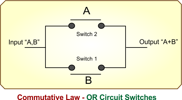
In the first circuit, switch A is placed before switch B. In the second circuit, switch B is placed before switch A. Both circuits produce the same output.
- Case 01: When A = 0 and B = 0, the output is 0.
- Case 02: When A = 0 and B = 1, the output is 1.
- Case 03: When A = 1 and B = 0, the output is 1.
- Case 04: When A = 1 and B = 1, the output is 1.
Therefore, changing the order of the switches does not change the output.
Commutative Law in Boolean Simplification
The Commutative Law is commonly used to change the order of variables in Boolean expressions without changing their value. Let’s explain some examples.
Commutative Law Example 1: A · B
The AND Commutative Law allows us to interchange A and B.
- A · B = B · A
Commutative Law Example 2: A + B
The OR Commutative Law allows us to interchange A and B.
- A + B = B + A
Commutative Law Example 3: AB + C
Using the AND Commutative Law, the variables inside the product term can be exchanged.
- AB + C = BA + C
Commutative Law Example 4: A + BC
Using the AND Commutative Law, B and C can be exchanged.
- A + BC = A + CB
Commutative Law Example 5: ABC
The order of variables in an AND operation can be changed without changing the result.
- ABC = BAC
- ABC = CBA
- ABC = BCA
Commutative Law Example 6: A + B + C
The order of variables in an OR operation can also be changed without changing the result.
- A + B + C = B + A + C
- A + B + C = C + B + A
- A + B + C = B + C + A