


OSI Model
- OSI stands for Open System Interconnection. It is a referencing model that describes how information moves from one computer to another computer over the internet.
- The OSI model was developed by the ISO (International Organization for Standardization) in 1984. It is now become a popular architectural model.
- OSI consists of seven layers, and each layer performs a particular task. Each layer is independent of the others in performing their tasks.
Characteristics of the OSI Model
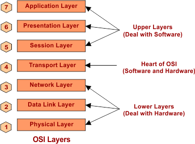
There are 7 layers of the OSI model, where the Physical is the first and the Application is the last layer. A list of OSI layers is given under,
- Physical Layer
- Data-Link Layer
- Network Layer
- Transport Layer
- Session Layer
- Presentation Layer
- Application Layer
Upper and Lower Layers
The Upper 3 layers (layer 5, 6, 7) of the OSI model mainly deals with the software, and the lower 3 layers (layer 1, 2, 3) deals with hardware. The intermediate layer (layer 4) deals with both hardware and software.
At Sender end the Application Layer is the first layer but at Receiver end, the Application layer is the 7th layer, as shown below,

Data Representation
The sender sends data to the Application layer. Data converted to segment at the Transport layer. Segment then converted to packets (TCP) or datagrams (UDP) at Network Layer. Packets are converted into Frames at the data link layer. Frames are converted into bits at the physical layer. Detail is given under

Functionalities of Different Layers
| Layer Name | Devices | Protocols of this layer | Delivery | Address |
| 7. Application Layer | Gateways, Firewalls, PCs, Phone,s etc. | SMTP, HTTP, FTP, DHCP, Telnet, POP3 etc. | – | – |
| 6. Presentation Layer | Firewalls etc. | SSL, MIME, MPEG, etc. | – | – |
| 5. Session Layer | Firewalls etc. | RPC, PAP, SAP, etc | – | – |
| 4. Transport Layer | Gateways, Firewalls, etc. | TCP, UDP, SCTP, etc | END to END | Port |
| 3. Network Layer | Routers, Brouter, etc | IP, IPV4, IPV6, ICMP,IGMP etc | Source to Destination | IP address |
| 2. Data-Link Layer | Bridges, Modem, NIC, etc. | IEEE 802.3, IEEE 802.5, RAPA, PPP, Frame Relay, CSMA etc. Ethernet, Wi-Fi, | Node to Node | MAC address |
| 1. Physical Layer | HUB, Cable, Repeaters, etc. | IEEE 802.11, ISDN | – | – |
Delivery of Data (Process)
As we see in the above table, the Delivery of data is further explained through the following diagram

Keep in mind:
- Node to Node (Hop to Hop) frames delivery is responsibility of Data link Layer.
- Source to destination (Host to Host) packets delivery is responsibility of Network Layer
- End to End (Process to Process OR Port to Port) Segments delivery is responsibility of Transport Layer
Further explanation of OSI layers in detail is explained in upcoming lectures.