


Channelization Protocols (Multiplexing)
In channelization Protocols, the available bandwidth of the medium is shared in time, shared in frequency, or shared in code for multiple stations to access the shared medium at a time.
Important: Channelization protocols are achieved through Multiplexing. Let’s explain channelization protocols through multiplexing.
- Time-division Multiplexing (TDM) channelizes the channel through different time slots.
- Frequency division Multiplexing (FDM) channelizes the channel through different frequencies.
- Wavelength division Multiplexing (WDM) channelizes the channel through different wavelengths.
- Code division Multiplexing (CDM) channelizes the channel through different codes.
Important:
|
Let’s explain multiplexing for a better understanding of channelization at the physical layer.
Multiplexing And It’s Types
“Multiplexers combine multiple signals into one signal, and DE-Multiplexers separate the multiplexed signals. So, multiplexing (combination of multiplexer and de-multiplexer) allows multiple signals from multiple users to share a common communication channel.”
In simple words, Multiplexing can defined as,
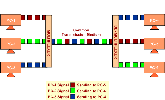
- When multiple senders try to send digital or analog signals over a single medium, a device called a Multiplexer allocates the physical channel to each.
- On the receiving end, a De-multiplexer receives data from a single medium, identifies each, and sends it to different receivers.
The following figure explains the technique of multiplexing.
Purpose of Multiplexing
The basic purpose of multiplexing is to share a single medium between multiple signals of different devices.
Note: The combination of different signals over the single medium does not mix with each other due to Modulation.
Types of Multiplexing
Signals are of two types, analog and digital, so we required multiplexing for both types of signals.

1. Frequency Division Multiplexing (FDM)
FDM is an analog technology which is used in radio and TV transmission. Every input signal is modulated with a carrier frequency to change its frequency (characteristics). A changed frequency signal is called frequency modulated. As explained under,
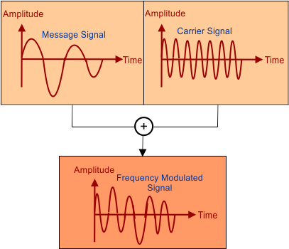
The following figure shows that Modulated signals are multiplexed and transmitted through common transmission media.

Note: Channels (different stations, i.e. mobile phones) are separated by guard bands. A guard band is a frequency that is not used by either any other channel.
2. Wavelength Division Multiplexing
Wavelength Division Multiplexing (WDM) is just like the frequency division multiplexing (FDM) except
- WDF Uses fiber optical modulated signals instead of frequency-modulated signals.
- It uses Fiber optic cable instead of any other medium.
As we know, light has different wavelengths (colors). For the purpose of modulation in fiber optic medium, multiple optical carrier signals are multiplexed with different input wavelengths.
- Multiplexing and De-multiplexing are achieved through the prism.
- Prism can perform the role of a multiplexer by combining the different optical signals to form a composite signal, and the composite signal is transmitted through an optical fiber cable.
- Prism can also perform de-multiplexing operations by separating different optical signals.

Note: To utilize the high data rate capability of fiber optic cable, WDM is used.
Keep In Mind: The relationship between frequency and wavelength is λ = c/f, where C is the velocity of light.
3. Time Division Multiplexing (TDM)
In TDM, every transmitter is assigned a specific time slot to transmit its signals. Each user can transmit data within the provided time slot only.

Types of TDM
There are two major types of TDM.
I. Synchronous TDM:
The time slots are fixed and assigned. If the sender (station) is not ready to send data in its time slot, then an empty slot is transmitted.

Note: In Synchronous TDM, Both ends, i.e., Multiplexer and De-multiplexer, are timely synchronized, and both switch to the next channel simultaneously.
II. Asynchronous TDM: It cannot send an empty slot in time if no signal has been transmitted.
The slots are allocated dynamically. If the sender (station) is not ready to send data in its time slot, then the data of that station, which is ready at that time, is transmitted. In this way, empty slots cannot be sent. So, it saves channel capacity.
In Asynchronous TDM, the sending of empty slots means there are no signals remaining to transmit.

Important: In synchronous TDM, if we have X input lines, then there must be an equal no of slots (Y) in one frame, So X=Y. but In asynchronous TDM, if we have X input lines, then the frame contains not more than Y slots, with Y less than K (Y < K).
4. Code Division Multiplexing (CDM)
We use carrier frequency signals to identify the signals in modulation uniquely. The alternative to this method is to use code division multiplexing, where every input signal is assigned a unique code.
After assigning the unique code to every input signal, multiplexing and de-multiplexing are used over a single medium to transmit data successfully.

Note: Code division multiplexing is a mathematical technique that does not use the physical properties of signal for data transmission over a single medium.
What is Demultiplexing?
Demultiplexing at the physical layer means separating combined signals (by time, frequency, or wavelength) so that each signal can be processed individually at higher layers.
How Demultiplexing Works
Imagine a fiber optic cable carrying data for 4 users:
- At the sender’s end, 4 signals are multiplexed using different wavelengths (colors).
- At the receiver’s end, a demultiplexer splits the light back into the 4 original wavelengths.
- Each signal is then sent to the correct receiver.
That’s demultiplexing at the physical layer, separating physical signals.