


Error Detection at the Data Link Layer
When data is transmitted from one device to another device, then the data may change during transmission. If the sending data is not identical to the receiving data, then it is the error state.
For reliable communication, errors must be detected and then corrected.
Note: Error Deduction and correction are implemented either at data link layer (layer 2) or transport layer (layer 3) of OSI Model.
Types of Errors
Errors can be classified into two categories
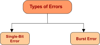
1. Single-Bit Error
If only one bit of transmitted data unit is changed i.e. from 1 to 0 or from 0 to 1 then it is a single bit error. The following figure shows the one-bit change,

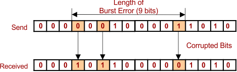
2. Burst Error
If two or more bits are changed (i.e., from 0 to 1 or from 1 to 0), then it is a Burst Error. The Burst Error is calculated from the first corrupted bit to the last corrupted bit.
How to Detect the Errors?
Error deduction means to decide whether the received data is correct or not without having a copy of original data.
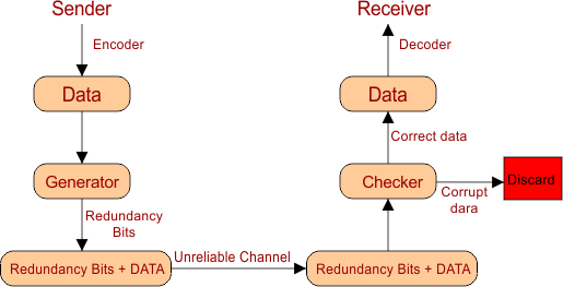
To detect or correct errors we need to send some extra bits along with original message (data). These extra bits are called redundant bits. To detect errors, we use Generator and Checker.
Generator: The generator is used at the sender end to generate redundancy bits. These redundancy bits are appended with sending data.
Checker: Checker is used at receiver end, it verify the data and redundancy bits. If sending information is unchanged, then data is accepted; otherwise, it is rejected.
Block diagram of error deduction is given below
Error Detecting Techniques
The most popular error-detecting techniques are
- Single parity check
- Two-dimensional parity check
- Checksum
- Cyclic redundancy check
1. Single Parity Check
- Single parity bit is also known as even parity bit or Vertical Redundancy Check (VRC)
- According to a single parity check, a parity bit, also known as the redundant bit, is appended at the end of the data unit so that the number of 1s becomes even.

- Before the transmission of bits, the 1’s bits are calculated by an even parity generator, which is also called compute the parity bit.
- At receiving end, again compute the parity bit, if the data still holds even parity bit then there is no error in data.
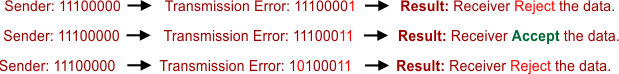
Performance Of Single Parity
- It can detect single-bit errors easily.
- It can detect burst errors only if the No. of errors is Odd. If even the number of bits changes, then it cannot detect errors.
2. Two-Dimensional (2-D) Parity Check
A Two-Dimensional Parity Check is also known as a Longitudinal Redundancy Check (LRC). It is the improved version of the single parity bit.
According to 2-D Parity Check
- All sending data is placed in the form of rows and columns.
- For even Parity, bits are calculated for each column, and redundant bits are attached to that column.
- The block of parity bits of each column acts as redundant bits.
Longitudinal Redundancy Check (LRC) – Example
Find the LRC for the sending data blocks 11100111 11011101 00111001 10101001 and determine the data that is transmitted.
Solution:
Step 01: First, generate LRC bits as given below

Step 02: Now attach LRC with original data and transmit to sender. The block diagram of LRC is given below

Performance of 2-D Parity Check
- It can detect the burst errors.
- If two bits are changed in exactly the same column, then errors cannot detected.
3. Checksum in Error Detection
A Checksum is a redundancy of bits that are appended with actual data for error detection.
At the sender side, the checksum is generated, and at the receiver side, the checksum is validated. The block diagram of the Checksum is given below.
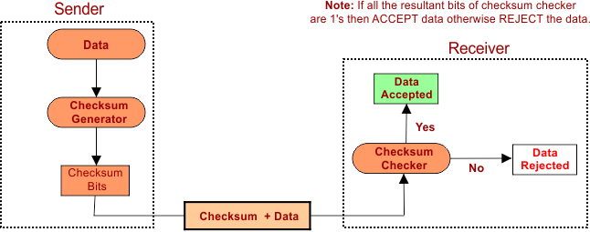
1. Checksum at Sender Side
At the sender side, a checksum is generated through the following steps
Step 01: Break the original data into the “K” number of blocks with “N” bits in each block.
Step 02: Sum all the “K” data blocks
Step 03: Add the carry bit if it exists.
Step 04: Find the 1st Complement
The result after 4th step, Checksum, is ready to append with data.
2. Checksum at the Receiver Side
For validation of data at the sender side, follow the following steps
Step 01: Sum all the “K” data blocks and Checksum
Step 02: Add carry bits if any
Step 03: If the result is all 1s, ACCEPT data; otherwise, REJECT the data.
Explain with Example
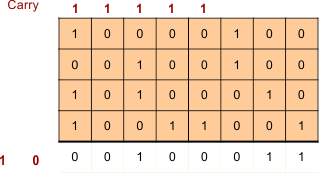
Consider the data unit 10011001111000100010010010000100. Now apply the above steps
1. Checksum Generator at the Sender Side
Step No 1: Break the original data into a “K” number of equal-sized blocks.
![]()
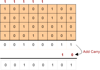
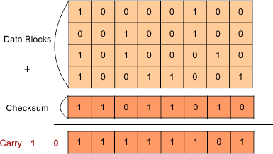
Step No 2: Sum all “K” Blocks
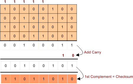
Step No 3: Add carry if any
Step No 4: Find the 1st Complement = Checksum
2. Checksum Validation at the Receiver Side
Step 01: Sum all the “K” data blocks and Checksum
Step 02: Add carry if any
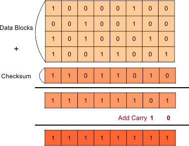
Step 03: If all the resultant bits of step 2 are 1’s, ACCEPT data otherwise, REJECT the data.
As we see, the result of step 2 is all 1’s, so data is accepted.
Performance of Checksum
- Checksum can detect even or odd bits changing.
- If one or more bits of a data block are changed and corresponding bits or bits of opposite value in a second block are also changed, the sum of those columns will not change. So, an error will not detect.
In the next lectures, we will explain all types of error-detecting techniques