


Physical Layer
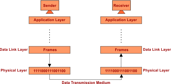
The physical layer is the last layer from the sender and the first layer from the receiving side in the OSI model.
Note: Generally we assume the numbering of OSI layers according to Receiver Side.
The Physical Layer transmits raw bits in the form of signals, which can be analog or digital, through a physical communication medium such as cables or wireless channels.
- It establishes, maintains, and terminates the physical connection of the network.
Functions Of the Physical Layer
Let explain the major tasks of physical layer in OSI model
1. Transmission Medium
At the Physical Layer, the transmission medium refers to the physical pathway through which data is transmitted. This can be:
- Wired: Cables like fiber optics, coaxial cables, or twisted pair cables.
- Wireless: Radio waves, microwaves, and infrared signals etc., are used for wireless communication. Various technologies like Wi-Fi, Bluetooth, and cellular networks use these signals. These signals enable devices to connect and transfer data over short to long distances without physical cables.
The medium carries the signals that represent data between devices.
2. Hardware
Here are common hardware devices used at the Physical Layer:
i.) Network Interface Card (NIC)
Network Interface card (NIC) is hardware component in computers or devices that connects them to a network. At physical layer, it converts digital data into signals for transmission over the network medium.
ii.) Cables (Fiber Optic, Coaxial, Twisted Pair)
Guided transmission media contains cables that can carry signals between devices. Each type varies in speed, distance, and resistance to interference.
iii.) Hubs
A basic networking device that connects multiple computers in a LAN. It broadcasts data to all connected devices without filtering.
iv.) Repeaters
Devices that receive, amplify, and retransmit signals to extend the communication range. Useful for overcoming signal attenuation in long-distance transmission.
v.) Modems
Convert digital signals to analog (and vice versa) for transmission over telephone lines. Commonly used for internet access over traditional phone networks.
vi.) Connectors and Jacks (e.g., RJ-45)
Physical interfaces used to connect cables to devices. RJ-45 is commonly used for Ethernet connections in LANs.
3. Data Transmission Mode
Data transmission modes defines the way data is transmitted between two devices in a network. It determines the direction of signal flow during communication.
- Simplex: Data flows in only one direction (e.g., keyboard to computer).
- Half-Duplex: Data flows in both directions, but only one at a time (e.g., walkie-talkies).
- Full-Duplex: Data flows in both directions at the same time (e.g., telephone).
4. Physical Topology
Physical topology defines the way network devices are arranged. The common network topologies are given below
i.) Bus Topology: All devices share a single communication line (the bus). It’s simple and cheap, but a cable failure can crash the whole network.
ii.) Star Topology: ll devices connect to a central hub or switch. Easy to manage, but if the hub fails, the whole network goes down.
iii.) Ring Topology: Devices are connected in a circular loop. Data travels in one direction, and a single device failure can affect the whole ring.
iv.) Mesh Topology: Each device is connected to every other device. Highly reliable, but costly and complex to install.
v.) Tree Topology: A mix of star and bus topologies in a hierarchical structure. It’s scalable but depends on the main backbone cable.
vi.) Hybrid Topology: Combines two or more different topologies. Flexible and efficient, but more complex to design and maintain.
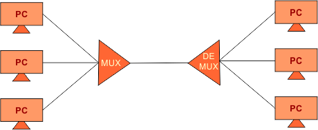
5. Multiplexing & De-Multiplexing
Multiplexing combines multiple data signals into one for efficient transmission over a shared medium. De-Multiplexing separates the combined signal back into individual streams at the receiver end. It helps in saving bandwidth and allows multiple devices to share the same channel. Common types include TDM, FDM, and WDM, used in networks and communication systems.
6. Encoding Schememes
Data to signal conversion is called encoding. Here are 4 main types of encoding schemes
- Digital Data to Digital Signal (Line Coding)
- Digital Data to Analog Signal (Digital Modulation)
- Analog Data to Digital Signal (Digitization)
- Analog Data to Analog Signal (Analog Modulation)
Encoding schemes at the Physical Layer make sure bits are reliably turned into signals, transmitted efficiently, and interpreted correctly by the receiver. Major tasks of encoding schemes at physical layer are given below
i.) Bit Representation as Signals
- Encoding translates digital bits (
0and1) into electrical, optical, or electromagnetic signals. - In NRZ (Non-Return to Zero),
1might be a high voltage and0a low voltage.
ii.) Synchronization
-
Ensures the receiver stays synchronized with the sender’s clock. Certain encoding schemes, such as Manchester, incorporate timing information, which facilitates alignment between the sender and receiver.
iii.) Efficient Use of Bandwidth (high data rates)
Good encoding schemes make optimal use of available bandwidth, balancing speed and reliability. For example, 8B/10B encoding takes 8 bits of data and turns it into 10 bits for transmission.
1v.) Minimize Transmission Errors
The Physical Layer uses techniques like signal encoding, shielding, and repeaters etc., to ensure signals are clear and strong, reducing noise, interference, and attenuation. This helps the data transmit correctly over distances without errors.
Note: Physical layer controls errors indirectly, but actually the error controls techniques are used in above layers of OSI model.