


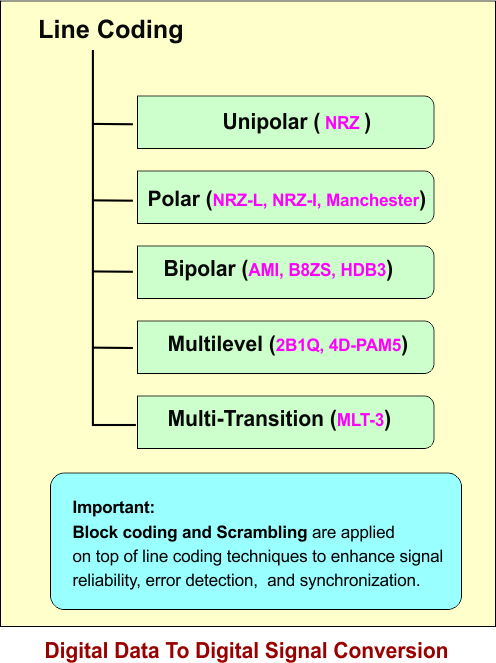
Digital Data To Digital Signal Conversion
Line coding is a technique used to convert digital data (composed of 0s and 1s) into a suitable digital signal—whether electrical, optical, or electromagnetic—that can be efficiently transmitted over mediums like copper cables, fiber-optic cables, or wireless channels.\
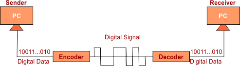
For example, line coding transforms binary data into signals for transmission across different mediums. In copper cables, it may employ electrical voltages, such as Manchester encoding. For fiber-optic cables it uses light pulses where “ON” represents 1 and “OFF” represents 0. In wireless communication, various modulation techniques like Amplitude Shift Keying (ASK) and Phase Shift Keying (PSK) use electromagnetic waves for transmitting signals.
Important Terms
- Data Element: A data element is the smallest piece of information that we want to send, i.e., bit 0 or 1.
- Signal Element: It is a shortest element of signal.
- Data Rate: Data elements are sent in one second. It is measured in bit/sec
- Signal Rate/Baud rate: Signal elements are sent in one second. SI unit is baud.
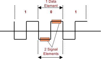
Important: Our basic need in encoding to transfer maximum bits (data element) per signal element. So, according to different encoding techniques (Explained below), one or more than one bit can be transferred in one signal element. Sometimes, more than one signal element is required to transmit one bit.
According to Manchester’s encoding, the following figure explains all the above factors.
Reasons for Line Coding
To resolve the following factors, we use the line coding
I. Bandwidth Problem
High bandwidth will be required when one digital bit is transferred through more than one element of the signal.
- For bit 0, half of the signal is represented by -V and half by zero voltage.
- for bit 1 half of the signal is represented by +V and half by zero voltage
- Example: Data = 01001.
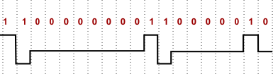
II. DC Problem
- Due to series of same bit values, a constant rate is generated. It is called the DC component, which is difficult to handle as in the following diagram continuous of 1. So to Eliminate the DC factor Line coding is used.
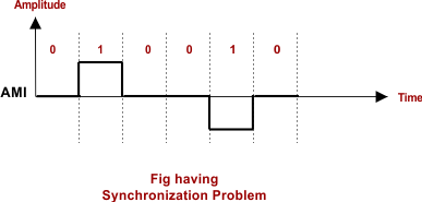
III. Synchronization Problem
When a digital signal represents its beginning, mid, and end for each digital bit, then there will be no synchronization problem. in the following diagram, there is no synchronization problem

However, in the following cases, there will be a problem with process synchronization because the midpoints of each signal element are not defined.
Types of Encoding Schemes
There are five main digital data-to-digital signal encoding schemes: Unipolar, Polar, Bipolar, Multilevel, and Multitransition. These names are based on the voltage levels and transitions used in the encoding process.
1. Uni Polar (NRZ)
The term “Uni” means “one,” indicating that only one type of voltage level—either positive or zero—is utilized. Typically, a positive voltage represents the data bit ‘1’, while 0V (ground) represents ‘0’. Since the system does not use negative voltages, it is referred to as unipolar. In Unipolar NRZ (Non-Return-to-Zero) encoding, the signal maintains a constant voltage level throughout the entire duration of each bit. The guidelines for drawing the signal are as follows:
-
Bit
1→ High Voltage (Positive Level)-
The signal remains at a high level (e.g.,
+V).
-
-
Bit
0→ Zero Voltage (Ground Level)-
The signal remains at
0V(no signal).
-
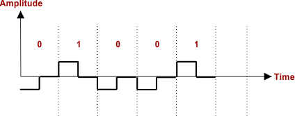
Example: Unipolar NRZ Signal
Let’s assume the binary data to be transmitted is:
0100110
Step-by-Step Signal Drawing
-
For
1→ Draw a straight horizontal line at a high voltage level (). -
For
0→ Draw a straight horizontal line at zero voltage.
Note: There is no transition in the middle of the bit period.

- Disadvantages: High DC component and poor synchronization.
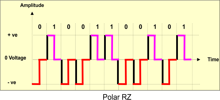
2. Polar RZ (Return-to-Zero) Encoding
The term “polar” refers to having two poles, which denote the two opposite voltage levels: positive and negative. In polar encoding, both of these voltage levels are used, allowing for the full range of voltages to be represented. It employs two distinct voltage levels—one positive and one negative.
In Polar RZ (Return-to-Zero) encoding, the same two voltage levels (positive and negative) are utilized as in Polar NRZ-L, but with an important difference: the signal returns to zero within each bit period.
Rules for Drawing a Signal
-
Bit 1 → Starts at a High Voltage (Positive Level, e.g., +V) and returns to zero within the bit period.
-
Bit 0 → Starts at a Low Voltage (Negative Level, e.g., -V) and returns to zero within the bit period.
-
The signal always transitions to zero in the middle of each bit duration.
Example: Polar RZ Signal
Let’s assume the binary data to be transmitted is:
01001100101
Step-by-Step Signal Drawing
-
For 1 → Start at +V, then return to 0 before the bit period ends.
-
For 0 → Start at -V, then return to 0 before the bit period ends.
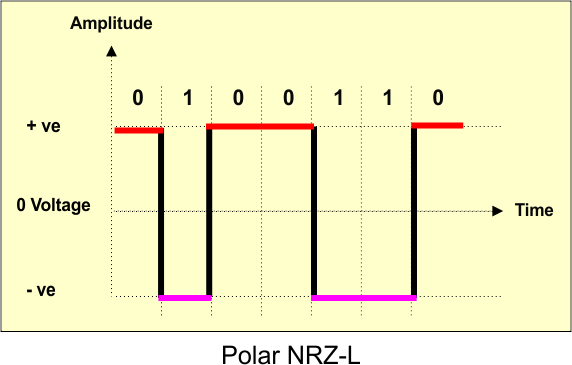
3. Polar NRZ-L
In Polar NRZ-L (Non-Return-to-Zero Level) encoding, two voltage levels, positive and negative, are utilized instead of only one. The signal maintains a constant voltage for the entire duration of the bit.
Rules for Drawing a Signal
-
Bit
1→ Low Voltage (Negative Level, e.g.,-V)-
The signal stays at a negative voltage.
-
- Bit
0→ High Voltage (Positive Level, e.g.,+V)-
The signal stays at a positive voltage.
-
Example: Polar NRZ-L Signal
Let’s assume the binary data to be transmitted is:
0100110
Step-by-Step Signal Drawing
-
For
1→ Draw a straight horizontal line at a negative voltage (-V). -
For
0→ Draw a straight horizontal line at a positive voltage (+V). -
There is no transition in the middle of the bit period.
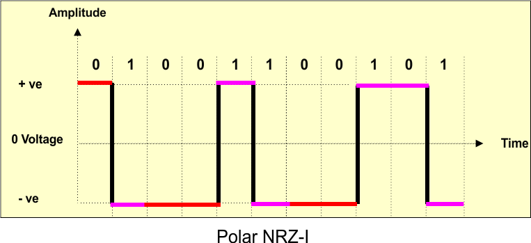
4. Polar NRZ-I
In NRZ-I (Non-Return-to-Zero Inverted), the signal is inverted only when a 1 is encountered. A 0 does not cause any change in the signal level.
Rules for Drawing a Signal
-
Bit
1→ Causes a transition (inversion) in the signal-
If the previous signal was high, it changes to low (-ve).
-
If the previous signal was low, it changes to high (+ve).
-
-
Bit
0→ No change in the signal level-
The signal remains the same as the previous bit.
-
| Important: In NRZ-I, the initial state can be either Low or High, but it must be predefined or agreed upon by the sender and receiver. |
Example: Polar NRZ-I Signal
Let’s assume the binary data to be transmitted is:
01001100101
- Start with +V
- 1 → causes a transition (invert signal)
- 0 → no change (retain previous level)
Step-by-Step Signal Drawing
| Bit Position | Bit | Signal Behavior | Signal Level (After Bit) |
|---|---|---|---|
| 1 | 0 | No change | +V |
| 2 | 1 | Transition (+V → –V) | –V |
| 3 | 0 | No change | –V |
| 4 | 0 | No change | –V |
| 5 | 1 | Transition (–V → +V) | +V |
| 6 | 1 | Transition (+V → –V) | –V |
| 7 | 0 | No change | –V |
| 8 | 0 | No change | –V |
| 9 | 1 | Transition (–V → +V) | +V |
| 10 | 0 | No change | +V |
| 11 | 1 | Transition (+V → –V) | –V |
The descriptive diagram is given below
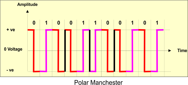
5. Polar Manchester Encoding
In Polar Manchester encoding, each bit period is split into two equal halves. A key feature of this encoding scheme is that a transition occurs in the middle of the bit period, ensuring synchronization.
Rules for Drawing a Signal
-
Bit 1 → High-to-Low Transition (Starts at +V and ends at -V within the bit period).
-
Bit 0 → Low-to-High Transition (Starts at -V and ends at +V within the bit period).
-
A transition always occurs in the middle of the bit period, ensuring synchronization.
Example: Polar Manchester Signal
Let’s assume the binary data to be transmitted is:
11010101
Step-by-Step Signal Drawing
- For 1 → The signal starts at +V for the first half of the bit period, then transitions to -V in the middle.
- For 0 → The signal starts at -V for the first half of the bit period, then transitions to +V in the middle.
This ensures that there is always a transition in the middle of each bit period, making clock synchronization easier. For 1 or 0, select one sign given diagram at a time.
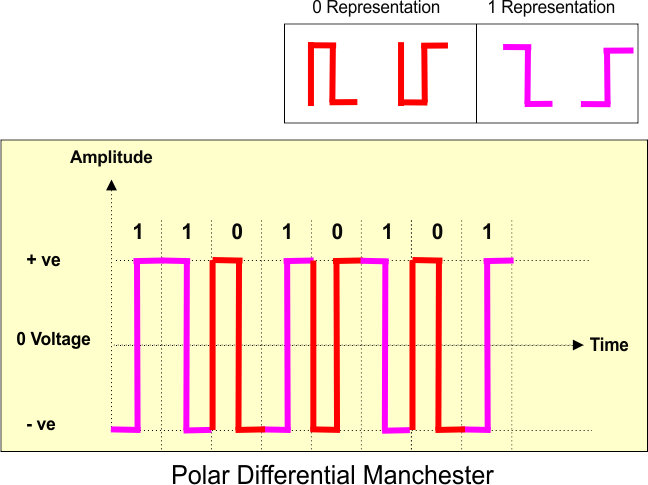
6. Polar Differential Manchester Encoding
In Polar Differential Manchester encoding, data is represented using transitions instead of absolute voltage levels. Each bit period is divided into two equal halves, and a transition always occurs in the middle of the bit period. The key distinction from Manchester encoding is that whether there is a transition at the beginning of the bit period indicates the value of the bit.
Rules for Drawing a Signal
- Bit 1 → No transition at the start of the bit period, but a mandatory transition in the middle.
- Bit 0 → A transition at the start of the bit period, plus the mandatory transition in the middle.
A transition always occurs in the middle of the bit period for synchronization. The encoding is based on differential signaling, meaning it depends on the previous bit rather than absolute voltage levels.
Example: Polar Differential Manchester Signal
Let’s assume the binary data to be transmitted is:
101001100101
Step-by-Step Signal Drawing
- For bit 1 → Maintain the same level as the previous bit at the start of the period, but a transition occurs in the middle.
- For bit 0 → A transition occurs at the start of the bit period, followed by another transition in the middle.
This encoding ensures that the signal does not depend on absolute voltage levels, making it immune to polarity reversals.
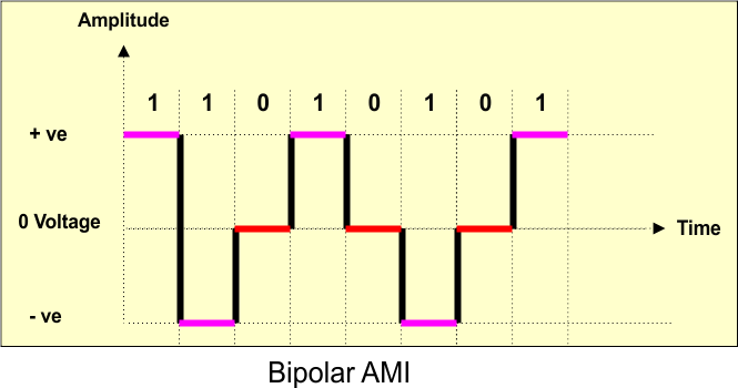
7. Bipolar AMI (Alternate Mark Inversion) Encoding
“Bi” refers to “two,” but in this context, it signifies three levels: positive, zero, and negative. Positive and negative voltages alternate, with zeros representing zero voltage. This alternating pattern eliminates DC bias and enhances synchronization.
Types:
- Alternate Mark Inversion (AMI):
1s alternate between +V and -V,0s are zero. - Pseudoternary:
0s alternate between +V and -V,1s are zero. - B8ZS (Bipolar 8-Zero Substitution): Replaces long sequences of 0s with a special pattern.
- HDB3 (High-Density Bipolar-3 Zeros): Similar to B8ZS but replaces four consecutive 0s.
In Bipolar AMI (Alternate Mark Inversion) encoding, three voltage levels are used: positive (+V), zero (0V), and negative (-V). Unlike polar encoding, where only two voltage levels exist, AMI assigns alternating polarities to successive “1” bits while keeping “0” bits at 0V.
Rules for Drawing a Signal
- Bit 1 → Alternates between +V and -V (Successive “1”s take opposite polarities).
- Bit 0 → Always represented by 0V (no voltage change).
There is no DC component, as “1” bits are equally distributed between +V and -V.
Example: Bipolar AMI Signal
Let’s assume the binary data to be transmitted is:
1 1010101
Step-by-Step Signal Drawing
- For bit 1 → The first “1” is assigned +V, the next “1” is assigned -V, and the alternation continues.
- For bit 0 → The signal remains at 0V (no voltage).
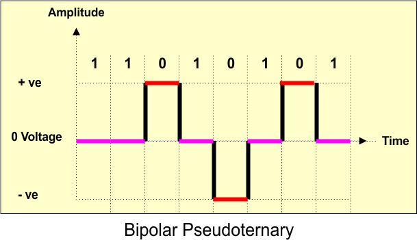
8. Bipolar Pseudoternary Encoding
In Bipolar Pseudoternary encoding, three voltage levels are used: positive (+V), zero (0V), and negative (-V), similar to Bipolar AMI. However, the key difference is in how bits are represented:
Rules for Drawing a Signal
-
Bit 0 → Alternates between +V and -V (Successive “0”s take opposite polarities).
-
Bit 1 → Always represented by 0V (no voltage change).
-
There is no DC component, as “0” bits are equally distributed between +V and -V.
Example: Bipolar Pseudoternary Signal
Let’s assume the binary data to be transmitted is:
11010101
Step-by-Step Signal Drawing
- For bit 1 → The signal remains at 0V (no voltage).
- For bit 0 → The first “0” is assigned +V, the next “0” is assigned -V, and the alternation continues.
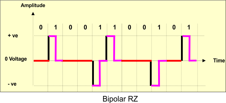
9. Bipolar RZ (Return-to-Zero) Encoding
In Bipolar Return-to-Zero (RZ) encoding, three voltage levels are used: positive (+V), zero (0V), and negative (-V). This encoding adheres to the Return-to-Zero principle, where each bit is represented by a voltage pulse that returns to zero midway through the bit period. The key distinction in this encoding method is how polarities are assigned to represent the bits.
Rules for Drawing a Signal
- Bit 1 → Alternates between +V and -V (Each “1” bit takes alternating polarities, and returns to zero within the bit period).
- Bit 0 → Always represented by 0V (no voltage change, and the signal stays at 0V for the entire bit period).
A transition occurs in the middle of each bit period, making the signal return to 0V at the end of each bit.
Example: Bipolar RZ Signal
Let’s assume the binary data to be transmitted is:
01001100101
Step-by-Step Signal Drawing
- For bit 1 → The first “1” is assigned +V, then the signal returns to 0V in the middle. The second “1” is assigned -V, then returns to 0V in the middle.
- For bit 0 → The signal stays at 0V throughout the bit period.
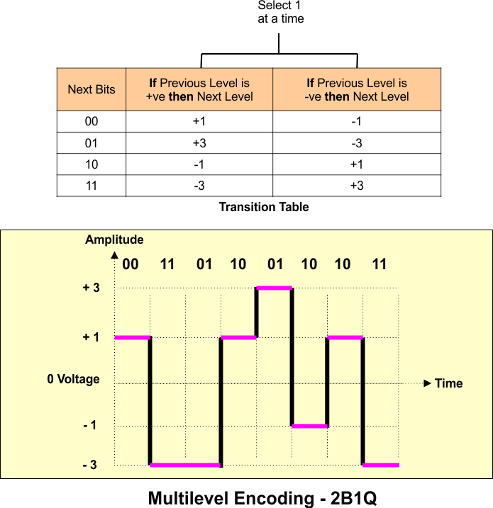
10. Multilevel Encoding – 2B1Q (Two-Binary-One-Quaternary)
“Multi” means more than two, referring to the fact that more than two voltage levels are used. Instead of representing just 0 and 1, multiple voltage levels allow encoding multiple bits per signal change. This improves bandwidth efficiency.
-
Example Schemes:
-
2B1Q (2 Binary 1 Quaternary): Each 2-bit pair is mapped to one of four voltage levels.
-
8B6T (8 Binary 6 Ternary): 8-bit data is encoded into 6 ternary (3-level) signals.
-
4D-PAM5 (Four-Dimensional 5-level Pulse Amplitude Modulation): Used in Gigabit Ethernet.
-
In Multilevel Encoding – 2B1Q (Two-Binary-One-Quaternary), two binary bits are encoded into one quaternary symbol, allowing the use of four distinct voltage levels to represent different combinations of bits. This technique is a form of multilevel signaling that improves bandwidth efficiency by transmitting two bits per symbol rather than just one.
Rules for Drawing a Signal
-
Each pair of bits (2B) is mapped to one of four voltage levels (1Q):
- 00 → -3V
- 01 → -1V
- 10 → +1V
- 11 → +3V
-
Each symbol (pair of bits) is represented by one voltage level, which remains constant throughout the bit period.
-
No transitions between bits, as each pair is represented by a specific voltage level for the entire duration of the bit period.
Example: Multilevel Encoding – 2B1Q Signal
11. Multi-transition Encoding – MLT-3
“Multi” means multiple, and “transition” refers to signal changes instead of voltage levels. Instead of focusing on voltage levels, this method optimizes the number of transitions to reduce bandwidth and power consumption. Used in Fast Ethernet (100BASE-TX).
-
Data is encoded using extra transitions to improve synchronization.
-
Example:
-
MLT-3 (Multilevel Transmission-3): Uses three voltage levels and cycles through them (+, 0, -) to represent
1s, reducing signal changes and bandwidth usage.
-
In MLT-3 (Multi-Level Transmit 3) encoding, a signaling technique that uses three voltage levels and ensures at least one transition per bit period, MLT-3 is a method designed to provide a way of transmitting binary data with minimal DC components while maintaining efficient bandwidth usage. The voltage levels alternate in a unique manner, providing a way to reduce the number of high voltage swings, which is useful in transmission over longer distances.
Rules for Drawing a Signal
-
MLT-3 uses three voltage levels:
-
+V (positive level)
-
0V (zero level)
-
-V (negative level)
-
-
The signal transitions between these three levels in a specific pattern:
-
A “1” bit causes a transition between levels, while a “0” bit does not cause a transition, keeping the signal at its current level.
-
The transitions alternate between positive and negative levels, cycling through +V → 0V → -V for successive “1” bits.
-
After a “1”, the next “1” causes the signal to transition to the next voltage level in the sequence (+V, 0V, -V).
-
A “0” bit simply maintains the current level without a transition.
-
Example: MLT-3 Signal
Let’s assume the binary data to be transmitted is:
01011011
Step-by-Step Signal Drawing
- For bit 1 → The signal transitions to the next level in the sequence (+V, 0V, -V).
- For bit 0 → The signal stays at the same level as the previous bit (no transition).

Characteristics of MLT-3 Encoding
-
Three Voltage Levels → Unlike NRZ or Manchester encoding, which use only two voltage levels (high and low), MLT-3 cycles through three levels:
-
+V (Positive Voltage)
-
0V (Zero)
-
-V (Negative Voltage)
-
-
Transition-Based Encoding →
-
A
1triggers a transition to the next voltage level in the cycle (+V → 0 → -V → 0 → +V …). -
A
0means no transition, and the voltage remains the same.
-
-
Reduced Signal Frequency → Because not every bit results in a transition, MLT-3 reduces the frequency of transitions, which leads to lower power consumption and less bandwidth usage than NRZ or Manchester encoding.
Table: Why Encoding Types Were Replaced
| Encoding Type | Advantages | Limitations | Where It Is Used Today | Why It Was Replaced |
|---|---|---|---|---|
| Unipolar Encoding (NRZ) | Simple, easy to implement | High DC component, poor synchronization | Rarely used today, mostly in low-speed internal circuits or basic digital logic circuits | Replaced by Polar & Bipolar due to poor synchronization and high power consumption |
| Polar Encoding (NRZ, RZ, Manchester, Differential Manchester) | Better synchronization, no DC in Manchester | High bandwidth requirement (Manchester), sync issues in NRZ | Manchester Encoding: Ethernet (10 Mbps, IEEE 802.3), RFID, low-speed communication networks | Replaced by Bipolar & Multilevel due to higher bandwidth needs and inefficiency in high-speed communication |
| Bipolar Encoding (AMI, B8ZS, HDB3) | No DC component, better than NRZ | More complex decoding, limited efficiency | AMI: Older telephone networks (T1, E1) B8ZS & HDB3: High-speed telecom (ISDN, T1/E1 circuits) | Replaced by Multilevel Encoding to increase data rates while reducing bandwidth |
| Multilevel Encoding (2B1Q, 8B6T, 4D-PAM5) | More bits per signal change, reduced bandwidth | Sensitive to noise, complex decoding | 2B1Q: DSL (Digital Subscriber Line) 8B6T: ISDN & Gigabit Ethernet 4D-PAM5: Gigabit Ethernet (1000BASE-T) | Replaced by Multitransition Encoding & Advanced Modulation to reduce power consumption and improve efficiency in high-speed networks |
| Multitransition Encoding (MLT-3) | Efficient bandwidth & power use, fewer transitions | Complex decoding, synchronization issues | MLT-3: Fast Ethernet (100BASE-TX), high-speed network cables | Still used, but being replaced in modern networks by fiber optics and higher-speed modulation (e.g., PAM4 in 400G Ethernet) |
Key Differences Among Encoding Schemes
| Encoding Type | How It Works | Synchronization | Bandwidth Efficiency | Error Detection | Why Used? | Why Replaced? | Currently Used In? |
|---|---|---|---|---|---|---|---|
| NRZ-L (Non-Return to Zero – Level) | 0 and 1 are represented by different voltage levels | ❌ No | ✅ High | ❌ Poor | Simple, low bandwidth usage | No clock recovery, long sequences of 0s or 1s cause sync issues | Not used in modern networks |
| NRZ-I (Non-Return to Zero – Invert on 1) | Voltage changes only on 1, remains same for 0 | ❌ No | ✅ High | ❌ Poor | Reduces sync issues slightly compared to NRZ-L | Still no clock recovery, long sequences of 0s cause sync loss | Not used in modern networks |
| Return to Zero (RZ) | Signal returns to zero between each bit | ✅ Yes | ❌ Requires more bandwidth | ❌ Poor | Helps with synchronization | Inefficient (twice the bandwidth needed), higher power consumption | Used in early telegraphy, not modern networks |
| Manchester Encoding | Transition in the middle of each bit period (0 = low-to-high, 1 = high-to-low) | ✅ Yes (Self-clocking) | ❌ Requires 2x bandwidth | ❌ None | Solves sync issues without an external clock | Requires double bandwidth, limiting speed | Used in 10 Mbps Ethernet (IEEE 802.3) |
| Differential Manchester Encoding | Transition at the start of the bit period for synchronization | ✅ Yes (Self-clocking) | ❌ Requires 2x bandwidth | ❌ None | More reliable in noisy environments | Still requires extra bandwidth, inefficient at high speeds | Used in older Token Ring networks |
| 4B/5B Encoding | Maps 4-bit data into 5-bit codes to ensure no long runs of 0s or 1s | ✅ Yes | ❌ Adds 25% overhead | ✅ Better error detection | More efficient than Manchester | Still wastes bandwidth due to extra bits | Used in Fast Ethernet (100 Mbps) |
| 8B/10B Encoding | Maps 8-bit data into 10-bit codes to balance the signal | ✅ Yes | ❌ Adds 25% overhead | ✅ Good | Ensures balanced signal and improves error detection | Overhead is too high for 1 Gbps+ speeds | Used in Gigabit Ethernet, Fibre Channel, PCIe 2.0+ |
| 64B/66B Scrambling | Converts 64-bit data into 66-bit codes with minimal overhead | ✅ Yes | ✅ High (only 3% overhead) | ✅ Excellent | Optimized for 10 Gbps+ speeds, low overhead | More complex processing but required for high speeds | Used in 10 Gbps+ Ethernet, PCIe 3.0+ |
| 128B/130B Scrambling | Maps 128-bit data into 130-bit codes for even lower overhead | ✅ Yes | ✅ Very High (1.5% overhead) | ✅ Excellent | High efficiency for ultra-fast networks | Complex processing required | Used in 25/50/100/400 Gbps Ethernet, USB 4.0 |