


Moore Machine
As we already covered the topics of DFA and NFA. DFA and NFA are the automata machines that take the input and do not give the output. Both DFA and NFA just check the acceptance of the given string. However, the Automata Moore Machine and Mealy also take the input and give the output. There is no final state in the Moore Machine.
Condition: For the Moore machine, there must be a dedicated path for each input from each state, like DFA.
Moore and Mealy machines take an input string (i.e., 11001) and give an output (i.e., aabbab).
- Each state of the Moore or Mealy machine gives an output. Output is denoted by the Output symbol.
- The initial state always gives an output. The remaining outputs depend on the transition function.
| Important: The output of the Moore machine is always one greater than the input. If the input length is three (i.e., 011), the output length will be four (i.e., aabb). Because the initial state always gives an output without an input. |
Formal Definition of Moore Machine
Moore and Mey machines accept all regular languages. Their output depends only on the machine’s current state, which is represented by the current state separated by “/.”
Moore machine can be described by 6 tuples (Q, q0, ∑, O, δ, λ) where,
- Q: a finite set of states
- q0: initial state of machine
- ∑: a finite set of input symbols
- O: output alphabet
- δ: transition function where Q × ∑ → Q
- λ: output function where Q → O
Moore Machine Example
Consider the following Moore Machine

Explanation of Moore Machine Tuples
Explanation of 6 tuples (Q, q0, ∑, δ, O, λ) is given below
- q0, q1, q2 are the states of the given Moore machine.
- q0 is the initial state.
- 0,1 are the inputs (∑) values for transition.
- The transition function is performed on input and gives a state move.
- O is the output, where a and b are output symbols that are separated by “/” from the state symbol.
- Output function (λ) gives the output. As in the above Moore Machine.
- Initial state q0 gives output “a”.
-
- If state q0 and input “1” are given, the state is changed to q1, and q1 will give the “b” output.
- In the same way, if state q1 and input “1” are given, then the state changes to q2, and q2 will give the “b” output.
-
- Similarly, if state q2 and input “0” are given, the state changes to q0, and q0 will give the “a” output. And so on…
Input to Output in Moore Machine
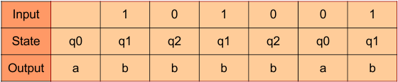
For instance, if the input “101001” is given to the above Moore machine, the output will be “abbbbab”. First, “a” of output comes without input. That’s why output is always greater than input length by 1. The remaining output comes after consuming each input. As shown in the following table.
Moore Transition Table
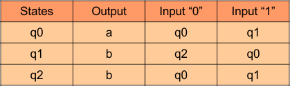
As q0 gives output “a”, q1 gives output “b”, and q2 gives output “b”. Transition for each input is also covered in the DFA and NFA table. So, the Transition table for given Moore Machine is given below.
Moore Machine Question-Based Examples
Let’s discuss more than 10 question based examples of Moore Machine
Moore Machine Example 01: 1’s Complement
Let’s design a Moore Machine that provides the first complement of any binary input. The 1’s complement operation means reversing every bit in a binary number, changing all 0’s to 1’s and all 1’s to 0’s. For example: If the input is 1010, then the output (1’s complement) is 0101.
Design of Moore Machine
To design a Moore machine for generating the 1’s complement, we use two states:
| State | Output | Meaning |
|---|---|---|
| q0 | 1 | Produces output 1 (used when input is 0) |
| q1 | 0 | Produces output 0 (used when input is 1) |
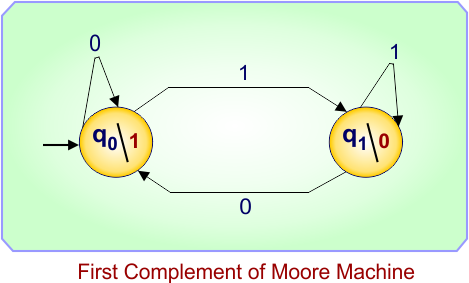
Moore Transition Diagram
Moore Transition Table
| Present State | Input = 0 | Input = 1 | Output |
|---|---|---|---|
| q0 | q0 | q1 | 1 |
| q1 | q0 | q1 | 0 |
Explanation
-
When the input bit is 0, the machine moves to q0, and the output is 1.
-
When the input bit is 1, the machine moves to q1, and the output is 0.
The machine changes states according to the input bit and gives the 1’s complement as output.
Moore Machine Example Execution
Let the input be 1 0 1 1.
| Input Bit | Next State | Output |
|---|---|---|
| 1 | q1 | 0 |
| 0 | q0 | 1 |
| 1 | q1 | 0 |
| 1 | q1 | 0 |
Final Output: 0 1 0 0
Moore Machine Example 02: 2’s Complement
To find the 2’s complement in a Moore machine, scan from LSB→MSB. Copy all bits up to and including the first 1 You see (this handles the “+1” by taking that 1 unchanged); after that first 1, output the bitwise complement (invert) of each remaining input bit. (Equivalent to: invert all bits, then add 1.)
The following table explains which states and outputs are used to construct the required Moore machine
| State | Output | Meaning |
|---|---|---|
| P0 | 0 | Pre-first-1 phase and this state will output 0 (used when the current input bit is 0) |
| P1 | 1 | Pre-first-1 phase and this state will output 1 (used when the current input bit is 1) — this state is reached when we output the first 1 (the inclusive copy of the first 1) and on the next input we switch to invert-phase |
| I0 | 1 | Invert (post-first-1) phase and this state outputs 1 (the inversion of input 0) |
| I1 | 0 | Invert (post-first-1) phase and this state outputs 0 (the inversion of input 1) |
(So P0/P1 = “still copying until first 1”; I0/I1 = “we are in invert-phase”. Each state’s output is the transformed bit for the current input that just caused the transition into that state.)
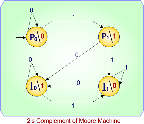
Moore Transition Diagram
Explanation of transitions
-
While in P0 (haven’t seen a 1 yet and current input was 0), if the next input is 0 we stay in P0 and output 0 (copying 0). If next input is 1 we go to P1 and output 1 (this is the first 1 we copy — it realizes the “+1”).
-
From P1 (we just emitted the first 1), on the next input we must switch to the invert phase: if next input is 0 → I0 (output 1), if next input is 1 → I1 (output 0).
-
In the invert phase (I0/I1) we stay in invert-phase: the state chosen corresponds to the inverted output for the current input (so I0 outputs 1 when input is 0, I1 outputs 0 when input is 1), and transitions keep you inside I0/I1 appropriately.
Moore Transition Table
| Present State | Input = 0 | Input = 1 | Output |
|---|---|---|---|
| P0 | P0 | P1 | 0 |
| P1 | I0 | I1 | 1 |
| I0 | I0 | I1 | 1 |
| I1 | I0 | I1 | 0 |
Example Working
Take the binary number 1011 (MSB→LSB). We will feed bits LSB→MSB into the machine: that stream is 1, 1, 0, 1.
Start in P0.
| Step | Input (LSB→MSB) | Transition (next state) | State Output (emitted bit) |
|---|---|---|---|
| 1 | 1 | P0 –1–> P1 | P1 outputs 1 |
| 2 | 1 | P1 –1–> I1 | I1 outputs 0 |
| 3 | 0 | I1 –0–> I0 | I0 outputs 1 |
| 4 | 1 | I0 –1–> I1 | I1 outputs 0 |
Outputs (LSB→MSB) = 1 0 1 0. Rewriting MSB→LSB gives 0 1 0 1, which is 0101 — the correct two’s complement of 1011.
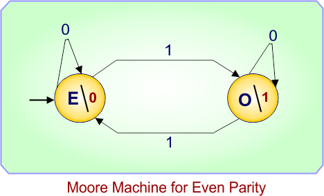
Moore Machine Example 03: Moore Machine for Even Parity (running parity bit)
The machine outputs the running even-parity (0 = even number of 1s seen so far; 1 = odd number of 1s seen so far).
For each input bit, the machine updates its parity state and emits the parity after reading that bit.
Design of the Moore Machine
We use two states:
| State | Output | Meaning |
|---|---|---|
| E | 0 | Even parity so far (emits 0) |
| O | 1 | Odd parity so far (emits 1) |
Moore Transition Diagram
Explanation
-
Reading a “0” does not change parity, so the machine stays in the same state and emits that state’s output.
-
Reading a “1” toggles parity: E → O (emit 1) or O → E (emit 0).
Moore Transition Table
| Present State | Input = 0 | Input = 1 | Output |
|---|---|---|---|
| E | E | O | 0 |
| O | O | E | 1 |
Moore Machine Example Execution
Let the input (MSB→LSB style) be 1 0 1 1. We feed bits left→right, and the machine starts in state E (even parity = 0).
| Step | Input | Transition (next state) | State Output (emitted bit) |
|---|---|---|---|
| 1 | 1 | E –1–> O | 1 |
| 2 | 0 | O –0–> O | 1 |
| 3 | 1 | O –1–> E | 0 |
| 4 | 1 | E –1–> O | 1 |
Final Output (for the input stream) = 1 1 0 1
(These are the running parity bits after each input — e.g., after reading the first 1 parity is odd → 1, after reading 1 0 parity remains odd → 1, etc.)
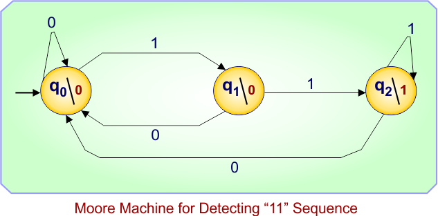
Moore Machine Example 04: Moore Machine for Detecting “11” Sequence
This Moore machine outputs 1 whenever the input sequence ends with two consecutive 1’s, otherwise it outputs 0.
In other words, the output becomes 1 after seeing “11” at the end of the input sequence.
Design of Moore Machine
We use three states:
| State | Output | Meaning |
|---|---|---|
| q0 | 0 | Initial state — no relevant pattern seen yet |
| q1 | 0 | The last input was 1, possible start of “11” |
| q2 | 1 | “11” detected (the last two inputs were both 1’s) |
Moore Transition Diagram
Explanation
From q0:
-
Input 0 → Stay in q0 (no pattern formed).
-
Input 1 → Move to q1 (we’ve seen one 1).
From q1:
-
Input 0 → Go back to q0 (pattern broken).
-
Input 1 → Move to q2 (we’ve seen “11”).
From q2:
-
Input 0 → Go back to q0 (pattern broken).
-
Input 1 → Stay in q2 (still ends in “11”).
The machine’s output depends only on the state — output 1 only when the last two bits were 1s.
Moore Transition Table
| Present State | Input = 0 | Input = 1 | Output |
|---|---|---|---|
| q0 | q0 | q1 | 0 |
| q1 | q0 | q2 | 0 |
| q2 | q0 | q2 | 1 |
Moore Machine Example Execution
Let the input be: 1 0 1 1 1 0
| Step | Input Bit | Transition (Next State) | State Output |
|---|---|---|---|
| 1 | 1 | q0 –1–> q1 | 0 |
| 2 | 0 | q1 –0–> q0 | 0 |
| 3 | 1 | q0 –1–> q1 | 0 |
| 4 | 1 | q1 –1–> q2 | 1 |
| 5 | 1 | q2 –1–> q2 | 1 |
| 6 | 0 | q2 –0–> q0 | 0 |
Final Output: 0 0 0 1 1 0
This machine “remembers” the last two input bits and lights up (output = 1) whenever the input ends with “11”.
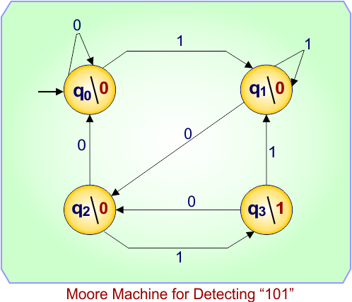
Moore Machine Example 05: Moore Machine for Detecting “101” Sequence
This Moore machine outputs 1 whenever the input sequence ends with “101”, otherwise it outputs 0.
Design of Moore Machine
We use four states:
| State | Output | Meaning |
|---|---|---|
| q0 | 0 | Start state — no relevant bits seen yet |
| q1 | 0 | Last input was 1 (possible start of “101”) |
| q2 | 0 | Last two inputs were “10” |
| q3 | 1 | Sequence “101” detected |
Moore Transition Diagram
Explanation
-
From q0:
-
0 → stay in q0
-
1 → go to q1 (saw start of pattern)
-
-
From q1:
-
0 → go to q2 (saw “10”)
-
1 → stay in q1 (still possible new pattern start)
-
-
From q2:
-
0 → back to q0 (pattern broken)
-
1 → go to q3 (saw “101”)
-
-
From q3:
-
On 0 → q2 (possible start of new pattern)
-
On 1 → q1 (restart search)
-
Moore Transition Table
| Present State | Input = 0 | Input = 1 | Output |
|---|---|---|---|
| q0 | q0 | q1 | 0 |
| q1 | q2 | q1 | 0 |
| q2 | q0 | q3 | 0 |
| q3 | q2 | q1 | 1 |
Moore Machine Example Execution
Input: 1 0 1 0 1 1
| Step | Input Bit | Transition (Next State) | State Output |
|---|---|---|---|
| 1 | 1 | q0 –1–> q1 | 0 |
| 2 | 0 | q1 –0–> q2 | 0 |
| 3 | 1 | q2 –1–> q3 | 1 |
| 4 | 0 | q3 –0–> q2 | 0 |
| 5 | 1 | q2 –1–> q3 | 1 |
| 6 | 1 | q3 –1–> q1 | 0 |
Final Output: 0 0 1 0 1 0
The output is 1 whenever the last three bits form “101”.
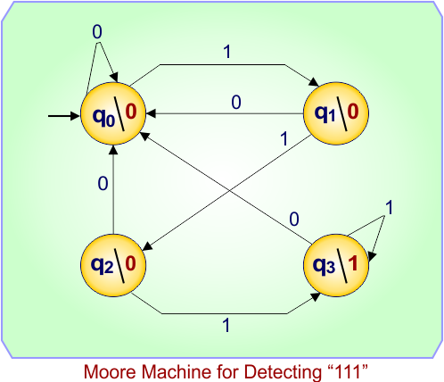
Moore Machine Example 6: Moore Machine for Detecting “111” Sequence
This Moore machine outputs 1 whenever the input ends with three consecutive 1s.
Design of Moore Machine
| State | Output | Meaning |
|---|---|---|
| q0 | 0 | Initial — no 1 seen yet |
| q1 | 0 | One 1 seen |
| q2 | 0 | Two 1s seen |
| q3 | 1 | “111” detected |
Moore Transition Diagram
Explanation
-
Every time three consecutive 1s appear, the machine enters q3 and outputs 1.
-
Any 0 resets the count (back to q0).
Moore Transition Table
| Present State | Input = 0 | Input = 1 | Output |
|---|---|---|---|
| q0 | q0 | q1 | 0 |
| q1 | q0 | q2 | 0 |
| q2 | q0 | q3 | 0 |
| q3 | q0 | q3 | 1 |
Moore Machine Example Execution
Input: 1 1 0 1 1 1 0
| Step | Input Bit | Transition (Next State) | State Output |
|---|---|---|---|
| 1 | 1 | q0 –1–> q1 | 0 |
| 2 | 1 | q1 –1–> q2 | 0 |
| 3 | 0 | q2 –0–> q0 | 0 |
| 4 | 1 | q0 –1–> q1 | 0 |
| 5 | 1 | q1 –1–> q2 | 0 |
| 6 | 1 | q2 –1–> q3 | 1 |
| 7 | 0 | q3 –0–> q0 | 0 |
Final Output: 0 0 0 0 0 1 0
Output = 1 when the last three bits are “111”.
Moore Machine Example 7: Moore Machine for Detecting “1001” Sequence
This Moore machine outputs 1 whenever the input sequence ends with “1001”.
Design of Moore Machine
| State | Output | Meaning |
|---|---|---|
| q0 | 0 | Start — no bits matched |
| q1 | 0 | “1” matched |
| q2 | 0 | “10” matched |
| q3 | 0 | “100” matched |
| q4 | 1 | “1001” detected |
Moore Transition Diagram
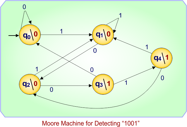
Explanation
-
From q0:
-
1 → q1 (start matching pattern)
-
-
From q1:
-
0 → q2 (“10” seen)
-
-
From q2:
-
0 → q3 (“100” seen)
-
-
From q3:
-
1 → q4 (“1001” detected)
-
-
From q4:
-
Pattern may overlap; next transitions maintain detection logic.
-
Moore Transition Table
| Present State | Input = 0 | Input = 1 | Output |
|---|---|---|---|
| q0 | q0 | q1 | 0 |
| q1 | q2 | q1 | 0 |
| q2 | q3 | q1 | 0 |
| q3 | q0 | q4 | 0 |
| q4 | q2 | q1 | 1 |
Moore Machine Example Execution
Input: 1 0 0 1 0 0 1
| Step | Input Bit | Transition (Next State) | State Output |
|---|---|---|---|
| 1 | 1 | q0 –1–> q1 | 0 |
| 2 | 0 | q1 –0–> q2 | 0 |
| 3 | 0 | q2 –0–> q3 | 0 |
| 4 | 1 | q3 –1–> q4 | 1 |
| 5 | 0 | q4 –0–> q2 | 0 |
| 6 | 0 | q2 –0–> q3 | 0 |
| 7 | 1 | q3 –1–> q4 | 1 |
Final Output: 0 0 0 1 0 0 1
The output is 1 when the sequence “1001” appears in the input.
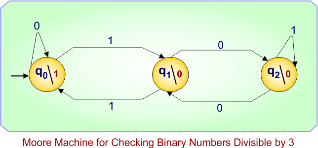
Moore Machine Example 08: Moore Machine for Checking Binary Numbers Divisible by 3
The Moore machine reads a binary number (MSB → LSB) and, after each input bit, outputs 1 if the number read so far is divisible by 3, otherwise 0.
Design of Moore Machine
We use three states representing the remainder (mod 3) of the binary value seen so far:
| State | Output | Meaning (Remainder mod 3) |
|---|---|---|
| q₀ | 1 | Number so far ≡ 0 (mod 3) — divisible by 3 |
| q₁ | 0 | Number so far ≡ 1 (mod 3) |
| q₂ | 0 | Number so far ≡ 2 (mod 3) |
Start state: q₀ (no bits read → value 0 → divisible by 3)
Moore Transition Diagram
Explanation
- When the next input bit is 0, the new remainder = (2 × old_remainder) mod 3.
- When the next input bit is 1, the new remainder = (2 × old_remainder + 1) mod 3.
- q₀ represents all numbers divisible by 3 and therefore produces output 1.
- q₁ and q₂ represent remainders 1 and 2, respectively, so their outputs are 0.
Moore Transition Table
| Present State | Input = 0 | Input = 1 | Output |
|---|---|---|---|
| q₀ | q₀ | q₁ | 1 |
| q₁ | q₂ | q₀ | 0 |
| q₂ | q₁ | q₂ | 0 |
Moore Machine Example Execution
Let the input (MSB→LSB) be 1 1 0, which is binary 110 = 6 (decimal).
Start in q₀.
| Step | Input Bit | Transition (Next State) | State Output |
|---|---|---|---|
| 1 | 1 | q₀ –1–> q₁ | 0 |
| 2 | 1 | q₁ –1–> q₀ | 1 |
| 3 | 0 | q₀ –0–> q₀ | 1 |
Final Output: 0 1 1
The final bit = 1 → the number 110₂ (= 6) is divisible by 3.
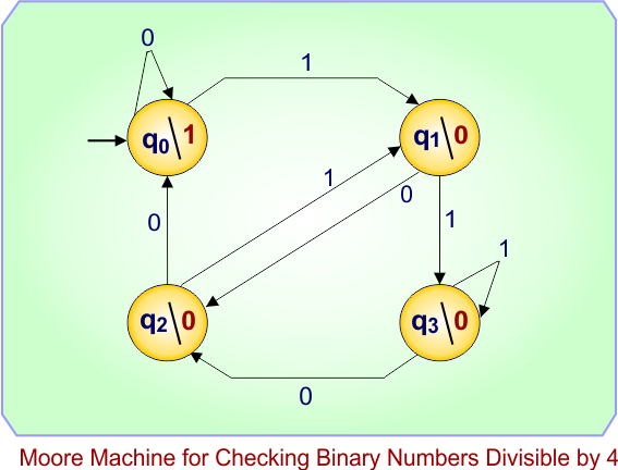
Moore Machine Example 09: Moore Machine for Checking Binary Numbers Divisible by 4
The Moore machine reads a binary number (MSB → LSB) and, after each input bit, outputs 1 if the number read so far is divisible by 4, otherwise 0.
Design of Moore Machine
A binary number is divisible by 4 if and only if its last two bits are 00.
So, this machine needs to “remember” the last two input bits.
We will use four states to represent the last two bits seen so far:
| State | Output | Meaning (last two bits) |
|---|---|---|
| q0 | 1 | Last two bits are 00 → divisible by 4 |
| q1 | 0 | Last two bits are 01 |
| q2 | 0 | Last two bits are 10 |
| q3 | 0 | Last two bits are 11 |
Start state: q0 (no bits read yet → assume last two bits = 00).
Moore Transition Diagram
Moore Transition Table
| Present State | Input = 0 | Input = 1 | Output |
|---|---|---|---|
| q0 | q0 | q1 | 1 |
| q1 | q2 | q3 | 0 |
| q2 | q0 | q1 | 0 |
| q3 | q2 | q3 | 0 |
Explanation
-
Each new input bit shifts the previous bits left and adds the new bit as the least significant bit (LSB).
-
The state represents the current last two bits.
-
Only q0 (last two bits = 00) produces output 1 since that’s the condition for divisibility by 4.
Moore Machine Example Execution
Let the input (MSB→LSB) be 1 0 0 → binary 100₂ = decimal 4.
Start in q0.
| Step | Input Bit | Transition (Next State) | State Output |
|---|---|---|---|
| 1 | 1 | q0 –1–> q1 | 0 |
| 2 | 0 | q1 –0–> q2 | 0 |
| 3 | 0 | q2 –0–> q0 | 1 |
Final Output: 0 0 1
The final output bit = 1, meaning 100₂ (4 in decimal) is divisible by 4.
Moore Machine Example 10: Moore Machine for Checking Binary Numbers Divisible by 5
The Moore machine reads a binary number (MSB → LSB) and, after each input bit, outputs 1 if the number read so far is divisible by 5, otherwise 0.
Design of Moore Machine
We use five states, each representing the remainder (mod 5) of the binary number read so far.
| State | Output | Meaning (Remainder mod 5) |
|---|---|---|
| q0 | 1 | Number so far ≡ 0 (mod 5) — divisible by 5 |
| q1 | 0 | Number so far ≡ 1 (mod 5) |
| q2 | 0 | Number so far ≡ 2 (mod 5) |
| q3 | 0 | Number so far ≡ 3 (mod 5) |
| q4 | 0 | Number so far ≡ 4 (mod 5) |
Start state: q0 (no bits read → value 0 → divisible by 5)
Moore Transition Table
The next remainder is computed using:
new_remainder = (2 × old_remainder + input_bit) mod 5
| Present State | Input = 0 | Input = 1 | Output |
|---|---|---|---|
| q0 | q0 | q1 | 1 |
| q1 | q2 | q3 | 0 |
| q2 | q4 | q0 | 0 |
| q3 | q1 | q2 | 0 |
| q4 | q3 | q4 | 0 |
Explanation
-
Appending a 0 doubles the number, so remainder ← (2 × remainder) mod 5.
-
Appending a 1 doubles and adds one, so remainder ← (2 × remainder + 1) mod 5.
-
q0 produces output 1 because it represents numbers divisible by 5.
-
All other states produce 0.
Moore Transition Diagram
updated soon..
Moore Machine Example Execution
Let the input (MSB→LSB) be 1 0 1 0, which is binary 1010₂ = decimal 10.
Start in q0.
| Step | Input Bit | Transition (Next State) | State Output |
|---|---|---|---|
| 1 | 1 | q0 –1–> q1 | 0 |
| 2 | 0 | q1 –0–> q2 | 0 |
| 3 | 1 | q2 –1–> q0 | 1 |
| 4 | 0 | q0 –0–> q0 | 1 |
Final Output: 0 0 1 1
The final output bit = 1, indicating that 1010₂ (= 10) is divisible by 5.
Moore Machine Example 11: Moore Machine for Checking Binary Numbers Divisible by 6
The Moore machine reads a binary number (MSB → LSB) and, after each input bit, outputs 1 if the number read so far is divisible by 6, otherwise 0.
Design of Moore Machine
Use six states representing the remainder (mod 6) of the binary value seen so far:
| State | Output | Meaning (remainder mod 6) |
|---|---|---|
| q0 | 1 | Number so far ≡ 0 (mod 6) — divisible by 6 |
| q1 | 0 | Number so far ≡ 1 (mod 6) |
| q2 | 0 | Number so far ≡ 2 (mod 6) |
| q3 | 0 | Number so far ≡ 3 (mod 6) |
| q4 | 0 | Number so far ≡ 4 (mod 6) |
| q5 | 0 | Number so far ≡ 5 (mod 6) |
Start state: q0 (no bits read → value 0 → divisible by 6)
Transition rule:
new_remainder = (2 × old_remainder + input_bit) mod 6
Moore Transition Table
| Present State | Input = 0 | Input = 1 | Output |
|---|---|---|---|
| q0 | q0 | q1 | 1 |
| q1 | q2 | q3 | 0 |
| q2 | q4 | q5 | 0 |
| q3 | q0 | q1 | 0 |
| q4 | q2 | q3 | 0 |
| q5 | q4 | q5 | 0 |
(Each entry computed as (2*r + b) mod 6, where r is remainder for the present state and b is the input bit.)
Explanation
-
Appending 0 doubles the current value: remainder ← (2 × remainder) mod 6.
-
Appending 1 doubles and adds one: remainder ← (2 × remainder + 1) mod 6.
-
q0 denotes divisibility by 6 and therefore emits 1; all other states emit 0.
Note: states q3 behaves like q0 under input 0 because 2×3 = 6 ≡ 0 (mod 6), and several states share similar transition patterns (this is expected from modular arithmetic).
Moore Machine Example Execution
Let the input (MSB→LSB) be 1 1 0, which is binary 110₂ = decimal 6.
Start in q0.
| Step | Input Bit | Transition (Next State) | State Output |
|---|---|---|---|
| 1 | 1 | q0 –1–> q1 | 0 |
| 2 | 1 | q1 –1–> q3 | 0 |
| 3 | 0 | q3 –0–> q0 | 1 |
Final Output: 0 0 1
The final emitted bit = 1, indicating 110₂ (6) is divisible by 6.