


Transition In Automata
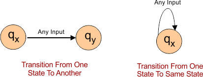
Moving From one state to another or in the same state with the help of an arrow, by using an input alphabet, is called transition in Automata. Transition happens with the help of the transition function.
Notation of Transition
The notation of a transition typically involves representing the states, input symbols, and corresponding transitions. Following is the notation of the transition from a state to a similar or another state.
Transition Table
- The first column represents all possible states.
- Rest all columns reserve for each corresponding input symbol. It is also called the next state after the transition for specific corresponding input symbols.
- The final state is represented by a star or double circle.
- The start state is always denoted by a small arrow.
Example: Transition in Automata
Consider the following DFA
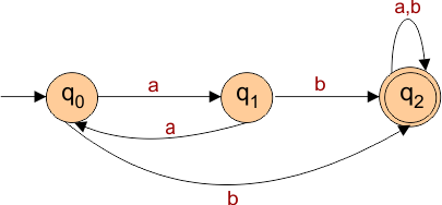
The following is the transition table of the above DFA
| Present State | Next state for Input “a” | Next State of Input “b” |
| →q0 | q1 | q2 |
| q1 | q0 | q2 |
| *q2 | q2 | q2 |
The above transition table has three rows displaying the present state and the next state depending on the input provided.
- In the first row, the current state is q0. On input “a”, the next state will be q1, and on input “b”, the next state will be q2.
- In the second row, the current state is q1. On input “a”, the next state will be q0, and on input “b”, the next state will be q2.
- In the third row, the current state is q2. On input “a”, the next state will be q2, and on input “b”, the next state will be q2.