











AND Gate Using NOR Gate
An AND logic Gate can be made using NOR logic gates. As we know, NOR is a universal logic gate, meaning it can be used to build other basic logic gates such as OR, AND, NOT, NAND, XOR, and XNOR. Implementing an AND gate using a NOR gate is useful when you need an AND logic circuit but only have NOR gates available; an AND logic gate is unavailable.
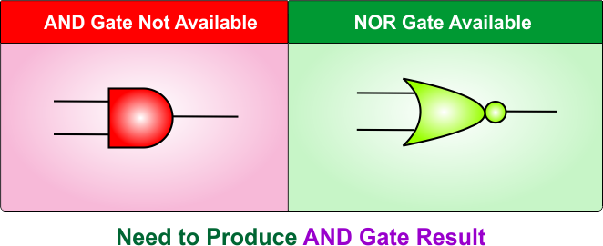
AND logic gate and a NOR logic gate, both are different in terms of output. So we have to implement NOR gate in such a way that its results are exactly similar to an AND logic gate.
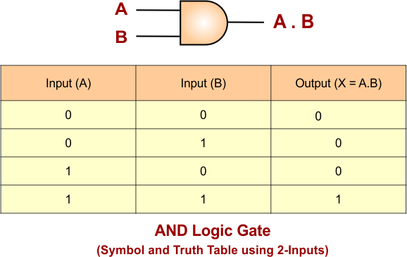
AND Logic Gate
An AND logic gate produces the output 1 (High) when all inputs are 1 (High). Output will becomes 0 (LOW) only the case when any inputs is 0 (LOW). AND Logic Gate Truth Table and its symbols are given below
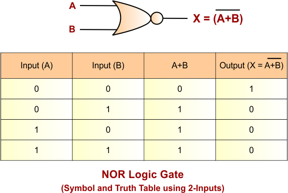
NOR Logic Gate
The NOR gate is a fundamental logic gate commonly used in digital logic design to perform the NOT-OR operation. It produces a HIGH output (1) only when all its inputs are LOW (0). If any input is HIGH (1), the output will be LOW (0).
If we want to construct an AND gate which contains a various number of inputs, then various numbers of NOR gates are required to implement this process. Let’s discuss various cases
AND Gate Using NOR Gate: 2-Input
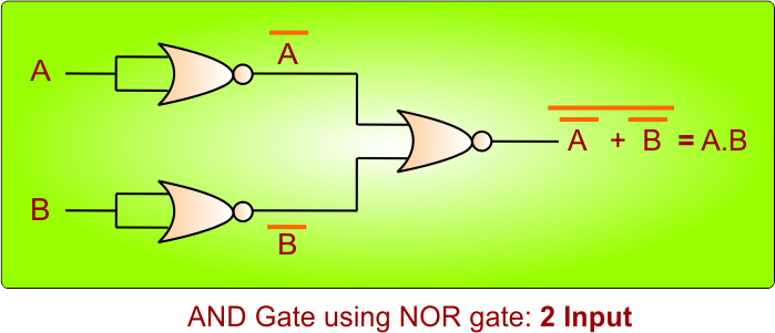
If we want to construct a 2-input OR logic gate using NOR gates, then 3 NOR gates are required to implement this process.
- First NOR gate: Takes “A” as an input, and the output is A’
- Second NOR gate: Takes “B” as an input, and the output is B’
- Third NOR gate: It takes the outputs of the first two NOR gates which is A’ , B’ as input and produces the result A.B by using De Morgan’s law.
The following diagram explains the process
AND Gate Using NOR Gate: 3-Input
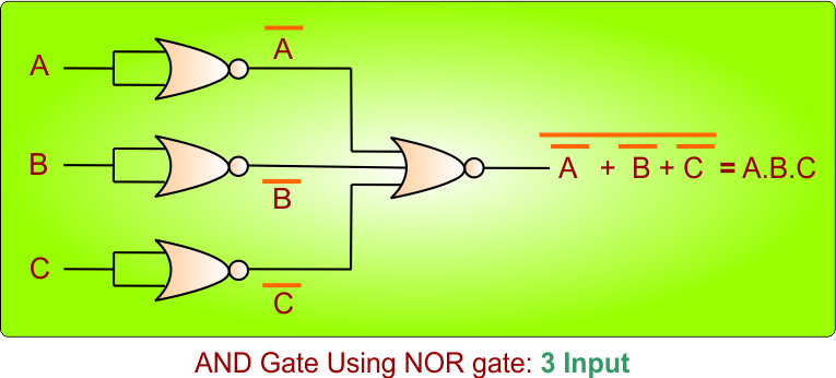
If we want to construct a 2-input OR logic gate using NOR gates, then 4 NOR gates are required to implement this process.
- First NOR gate: Takes “A” as an input, and the output is A’
- Second NOR gate: Takes “B” as an input, and the output is B’
- Third NOR gate: Takes “C” as an input, and the output is C’
- 4th NOR gate: It takes the output of the first three NOR gates which is A’ , B’ , C’ as a input and produce the the result A.B.C by using De Morgan’s law.
The following diagram explains the process
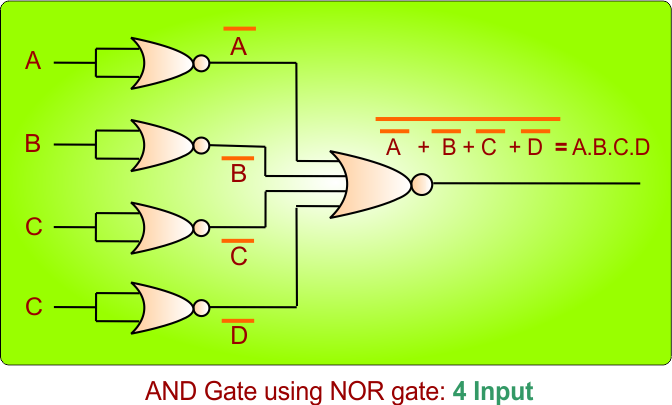
AND Gate Using NOR Gate: 4-Input
If we want to construct a 2-input OR logic gate using NOR gates, then 5 NOR gates are required to implement this process.
- First NOR gate: Takes “A” as an input, and the output is A’
- Second NOR gate: Takes “B” as an input, and the output is B’
- Third NOR gate: Takes “C” as an input, and the output is C’
- 4th NOR gate: Takes “D” as an input, and the output is D’
- 5th NOR gate: It takes the output of the first three NOR gates which is A’ , B’ , C’ , D’ as a input and produces the result A.B.C.D by using De Morgan’s law.
The following diagram explains the process