


ER Model in DBMS
In the world of Database Management Systems (DBMS), the Entity-Relationship (ER) model plays a vital role in how data is structured and organized. It provides a blueprint for designing databases that are both efficient and scalable. In this article, we will explore the ER model, its components, advantages, and how it contributes to effective database design.
- The Entity-Relationship (ER) model is a conceptual framework used to structure and define the relationships between data entities in a database.
- It was introduced by Peter Chen in 1976.
- The model uses a graphical approach to represent data and their relationships.
- It helps database designers visualize the structure of a database before implementation.
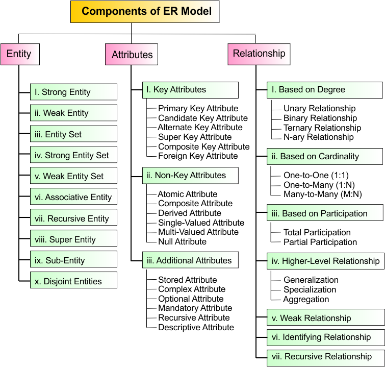
Components of the ER Model
The ER model is made up of several key components that are essential to understanding the structure and relationship of data. Here is the list of three main components with their subtypes in the ER Model
Symbols In ER Model
ER diagrams consist of various symbols, each represented by specific notation..
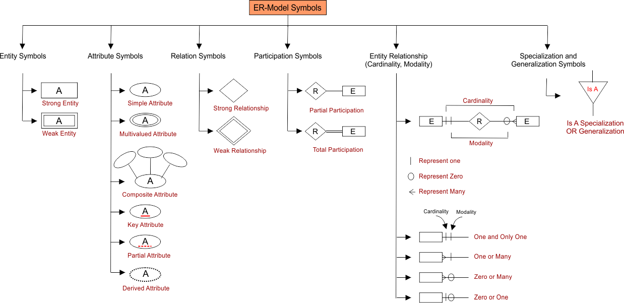
List all types of components in the ER model, including their names, symbols, and notations.
| Name | Symbol Name | Graphical Notation |
|---|---|---|
| Entity (Strong) | Rectangle |  |
| Weak Entity | Double Rectangle |  |
| Attribute (Simple) | Ellipse |  |
| Multivalued Attribute | Double Ellipse |  |
| Derived Attribute | Dashed Ellipse |  |
| Composite Attribute | Ellipse with sub-ellipses | 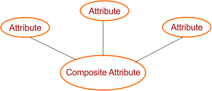 |
| Key Attribute | Underlined Ellipse |  |
| Relationship (Regular) | Diamond |  |
| Identifying Relationship (for Weak Entity) | Double Diamond | 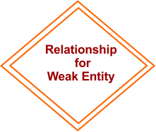 |
| Recursive Relationship | Diamond with a loop | 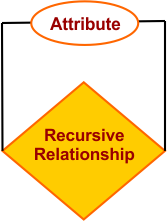 |
| Generalization | Triangle (upward) | 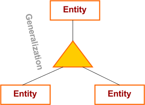 |
| Specialization | Triangle (downward) | 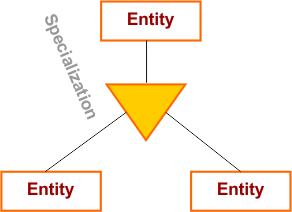 |
| Aggregation | Diamond inside Rectangle | 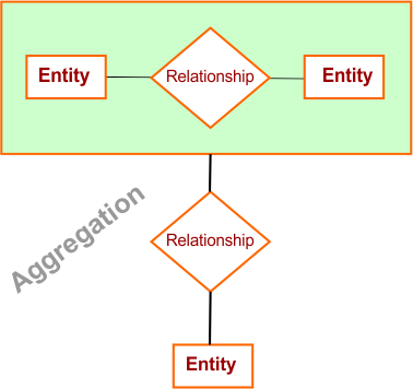 |
| Total Participation | Double line connection | 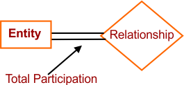 |
| Partial Participation | Single line connection | 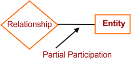 |
| One-to-One Relationship | Notation on connecting lines | 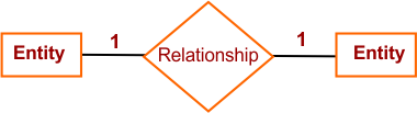 |
| One-to-Many Relationship | Notation on connecting lines | 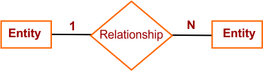 |
| Many-to-Many Relationship | Notation on connecting lines | 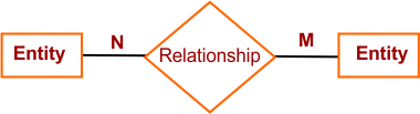 |
Let’s explain all major types of components used in ER model in detail
1. Entity
An Entity is a real-world object or concept that is distinguishable from other objects and has attributes. Entities represent objects that need to be stored in the database. For Example, A student is an entity in a school database.
Here is the list of various types of entities in DBMS
i. Strong Entity
- Exists independently in the database.
- Always has a primary key that uniquely identifies each record.
- Example: Student (Student_ID)
ii. Weak Entity
- Cannot be uniquely identified by its own attributes.
- Depends on a Strong Entity for identification.
- Uses a partial key + strong entity’s key.
- Example: Order_Item depends on Order.
iii. Entity Set
- A collection of similar entities that share the same attributes.
- Example: All students in a university database form the Student Entity Set.
iv. Strong Entity Set
- A set of strong entities.
- Each member has a unique primary key.
- Example: The Employee entity set (with Emp_ID).
v. Weak Entity Set
- A set of weak entities.
- Needs to be linked with a strong entity set via a relationship.
- Example: The Dependent entity set in HR database (depends on Employee).
vi. Associative Entity (Bridge Entity / Intersection Entity)
- An entity that represents a relationship between two entities.
- Useful in resolving many-to-many relationships.
- Example: Enrollment entity links Student and Course.
vii. Recursive Entity
- An entity that has a relationship with itself.
- Example: In an Employee table, one employee can be a Manager of another employee.
viii. Super Entity
- A generalized entity that contains common attributes shared by multiple sub-entities.
- Example: Person can be a super-entity for Student and Teacher.
ix. Sub-Entity (Subtype / Specialized Entity)
- An entity that inherits attributes from a super-entity but also has its own unique attributes.
- Example: Student and Teacher are sub-entities of Person.
x. Covering / Disjoint Entities
-
Disjoint entities: Sub-entities do not overlap (a record belongs to only one subtype).
-
Example: A Vehicle entity has disjoint subtypes → Car or Bike.
-
-
Overlapping entities: Sub-entities can share attributes (a record may belong to multiple subtypes).
-
Example: A Person can be both a Student and an Employee.
-
2. Attributes
Attributes describe the properties or characteristics of an entity. For Example, a Student entity may have attributes like Student_ID, Name, Age, and Address.
Attributes are of two major types, explained below
i. Key Attributes
Key attributes uniquely identify each entity in a database. Here is the list of key attributes
- Primary Key Attribute: Uniquely identifies each record. For Example: Student_ID, Emp_ID
- Candidate Key Attribute: Attributes that can potentially serve as a primary key. For Example: {Student_ID, Email} in Student table
- Alternate Key Attribute: Candidate keys not chosen as the primary key. For Example, If Student_ID is PK, then Email becomes an alternate key
- Super Key Attribute: Any set of attributes that uniquely identify a row (may include redundancy).For Example: {Student_ID, Name}, {Email}, {Phone + Student_ID}
- Composite Key Attribute: A Combination of 2 or more attributes to uniquely identify a record. For Example: {Course_ID, Student_ID} in Enrollment table
- Foreign Key Attribute: Attribute referencing the primary key of another table. For Example: Dept_ID in Employee table references Dept_ID in the Department table
ii. Non-Key Attributes
Non-key attributes describe properties of an entity but do not uniquely identify it. Here is the list of non-key attributes
- Simple / Atomic Attribute: Cannot be further divided. For Example: Age, Gender
- Composite Attribute: can be broken into subparts. For Example: Full_Name First_Name + Last_Name
- Derived Attribute: Value derived from other attributes. For example: Age (from Date_of_Birth)
- Single-Valued Attribute: Holds only one value per entity. For example: Date_of_Birth, Emp_ID
- Multi-Valued Attribute: Can hold multiple values. ForExample: Phone_Numbers, Skills
- Null Attribute: Represents missing/unknown values. For Example: Email (if not provided), Middle_Name (if not applicable)
3. Additional Attribute Types (Other Classifications)
Here are some additional attributes in DBMS
- Stored Attribute: Physically stored in the database as actual data. It is the opposite of derived attributes. Example: Date_of_Birth, Salary.
- Complex Attribute: Formed by combining composite and multivalued attributes. Helps represent detailed and repeated information together. Example: Educational_Qualifications → (Degree + University + Year).
- Optional Attribute: May or may not have a value in the entity. Such attributes can accept NULL values. Example: Middle_Name, Secondary_Email.
- Mandatory Attribute: Must always have a value for every record. These attributes are defined as NOT NULL in DBMS. Example: Student_ID, Employee_ID.
- Recursive Attribute: Points back to the same entity in a recursive relationship. Used to represent hierarchy within one entity set. Example: Manager_ID in Employee entity.
- Descriptive Attribute (of Relationship): An attribute that belongs to a relationship, not an entity. Provides additional details about the association. Example: Hours in Works_On (Employee–Project).
3. Relationship
A Relationship is an association between two or more entities. It shows how entities are connected. For Example, A student enrolls in a course (Student ↔ Course).
Here is the list of relationships in DBMS
i. Based on Degree (Number of Entities Involved)
-
A Unary (Recursive) relationship occurs when an entity is related to itself. For example, an employee can manage another employee, or a student can tutor another student. This shows self-relationship within the same entity set.
-
A Binary relationship is the most common relationship in DBMS, where two entities are associated with each other. For example, a student enrolls in a course or a teacher teaches a subject.
-
A Ternary relationship involves three different entities participating in a single association. For example, a doctor prescribes a medicine to a patient, where all three entities are connected in one relationship.
-
An N-ary relationship is a general form where more than three entities are involved together. For example, a supplier provides products to a warehouse for delivery to customers, involving multiple entities at once.
ii. Based on Cardinality (Cardinality Constraints)
Cardinality (also called cardinality ratio or cardinality constraint) defines how many instances of one entity can/must be associated with instances of another entity in a relationship.
There are two basic options for participation:
- One (1) – only one instance can participate.
- Many (N or M) – multiple instances can participate.
By combining these, we get the types of cardinality ratios. Here are major types of cardinality in DBMS are given below
- One-to-One (1:1) Relationship: One entity instance is related to only one instance of another entity.
-
Example: A Person can have only one Passport, and one Passport is issued to only one Person.
-
- One-to-Many (1:N) Relationship: A single entity instance is related to many instances of another entity.
-
Example: A Teacher can teach many Students. However, each student is taught by only one teacher (in that scenario).
-
- Many-to-One (N:1) Relationship: Many entity instances are related to one instance of another entity.
-
Example : Many Employees work in one Department. But each Department can have multiple Employees.
-
- Many-to-Many (M:N) Relationship: Multiple instances of one entity are related to multiple instances of another entity.
- Example: A Student can enroll in many Courses. Each Course can have many Students.
iii. Modality in DBMS
In DBMS, modality (also called minimum cardinality or participation constraint) specifies the minimum number of times an entity must participate in a relationship.
Types of Modality:
- a). Zero (0) → Optional Participation. It meentity may or may not participate.
-
Example: An Employee may not manage any Project.b).
-
- One (1) → Mandatory Participation
-
The entity must participate at least once.
-
Example: A Student must enroll in at least one Cours
-
iv. Cardinality and Modality combine in DBMS
When combined with Cardinality (maximum) and Modality (minimum), participation constraints become more precise.
- Maximum Participation (Cardinality): Defines the maximum number of times an entity can participate:
- 1 → One
- N → Many
- Minimum Participation (Modality): Defines the minimum number of times an entity must participate:
- 0 → Optional
- 1 → Mandatory
Finally, answer by combining both cardinality and modality
-
(0,1): Optional and at most one.
Example: An Employee may or may not have a Company Car, but only one. -
(1,1): Mandatory and exactly one.
Example: A Citizen must have exactly one National ID. -
(0,N): Optional and many.
Example: An Author may write no books or many books. -
(1,N): Mandatory and many.
Example: A Student must enroll in at least one Course but can take many.
vi. Participation / Minimum Cardinality
- Total Participation occurs when every entity in a set must take part in the relationship. For example, every Student must enroll in at least one Course, making their participation compulsory.
- Partial Participation happens when only some entities are involved in the relationship, while others are not. For instance, some Employees may not manage any Project, so their participation is optional.
v. Weak Relationship
A Weak Relationship exists when a weak entity cannot be uniquely identified without depending on a strong entity. It combines the primary key of the strong entity with its own attributes (called a partial key) to create uniqueness. Key Points:
- A weak entity does not have a complete primary key of its own.
- It depends on the strong entity for identification.
- A weak relationship is often represented with a double diamond in ER diagrams.
- Example: Order ↔ Order_Item (Order_Item cannot exist without Order).
vi. Identifying vs. Non-Identifying Relationship
- An Identifying Relationship occurs when the child entity cannot exist without the parent entity, meaning its primary key includes the parent’s primary key as a foreign key. For example, an Order Item cannot exist without an Order, and the Order ID becomes part of the Order Item’s primary key.
- A Non-Identifying Relationship happens when the child entity can exist independently of the parent, where the foreign key is not part of its primary key. For instance, an Employee belongs to a Department, but the Employee ID is independent and does not rely on the Department’s primary key.
v. Recursive / Self-Referencing Relationship
A Recursive (Self-Referencing) Relationship occurs when an entity is related to itself within the same entity set. For example, an Employee can act as a Manager of another Employee, showing a hierarchy within the same entity. While this type is technically a form of a Unary relationship, many DBMS books classify it separately due to its importance in representing real-world hierarchical or self-linked structures.
vii. Higher-Level Relationships (Abstraction)
- Generalization is the process of combining two or more lower-level entities into a higher-level entity. For example, a Car and a Truck can be generalized into a broader entity called a Vehicle.
- Specialization is the reverse of generalization, where a higher-level entity is divided into sub-entities based on specific attributes. For instance, an Employee entity can be specialized into a Teacher and an Engineer.
- Aggregation is a concept where a relationship itself is treated as an entity and participates in another relationship. For example, the relationship Instructor teaches Course can be aggregated and linked with Department.
- Inheritance in ER models is usually covered under Specialization/Generalization (Is-A hierarchy).
It means lower-level entities inherit the attributes of higher-level entities.
Example: Teacher and Engineer inherit attributes from Employee.
- Inheritance in ER models is usually covered under Specialization/Generalization (Is-A hierarchy).
Advantages of Using the ER Model
The ER model offers several benefits that make it a preferred choice for database design:
- Clear and Simple Representation: The graphical nature of the ER diagram makes it easy to visualize the data structure, entities, and relationships, offering a clear blueprint for database design.
- Helps in Database Normalization: The ER model helps in normalizing databases, which reduces redundancy and improves data integrity by breaking down data into manageable pieces.
- Facilitates Database Design: It helps in planning the structure of the database before implementation, saving time and effort during the development phase.
- Improved Communication: The ER diagram serves as a common language between stakeholders, making it easier for developers, analysts, and business users to collaborate and understand the system.
How to Create an ER Diagram
Creating a simple ER diagram involves several steps:
- Identify Entities: Start by identifying all the key entities in your system, such as students, courses, employees, etc.
- Define Attributes: Next, define the attributes for each entity. These attributes will describe the properties of each entity.
- Establish Relationships: Identify how entities are related to each other. Draw relationships between entities to represent their connections (one-to-one, one-to-many, or many-to-many).
- Assign Primary Keys: Choose a unique primary key for each entity to ensure each instance can be uniquely identified.
- Draw the ER Diagram: Use a diagramming tool like Microsoft Visio, Lucidchart, or draw.io to create the ER diagram. The diagram should include entities, attributes, relationships, and primary keys.
ER Model vs Relational Model: Key Differences
Although the ER model is used for designing databases, it is often converted into the relational model during the actual implementation phase. Here are the key differences: ER Model is used during the design phase, while the relational model is used during the implementation phase. In the ER model, relationships between entities are directly represented, while in the relational model, these relationships are represented through foreign keys.
Conclusion
The Entity-Relationship (ER) model is an essential tool for database design that allows you to create well-structured databases with clear and efficient relationships. By utilizing ER diagrams, database designers can visualize the structure, identify entities and their relationships, and ensure data integrity and efficiency. Whether you are designing a small-scale application or a large-scale enterprise system, understanding the ER model will help you create a robust foundation for your database.