


Relationships in ER Model
In the Entity-Relationship (ER) Model, relationships represent associations among two or more entities. They describe how entities interact with one another in a database.
In ER diagrams:
- Entities are represented by rectangles.
- Relationships are shown as diamonds.
- Attributes are ovals connected to entities or relationships.
For example: In a university database, the Student and Course entities can be related by a Registers relationship. Here are the major types of relationships in RDBMS
1) Cardinality / Maximum Cardinality
Cardinality in database design refers to the number of possible relationships between rows in two tables. When we say “based on cardinality (max),” we are classifying relationships by their maximum allowed connections between records.
There are three main types of relationships based on maximum cardinality:
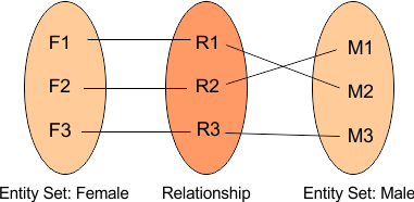
i. One-to-One (1:1) Relationship
A One-to-One (1:1) relationship means that each record in Table A may be related to zero or one record in Table B, and each record in Table B may be related to zero or one record in Table A.
The concept of cardinality refers to the maximum count of elements allowed, which can be at most one, rather than addressing the minimum count.
For example, One Female can marry only one Male

We can represent the above diagram in the following diagram
Implementation
Sometimes, the two entities can be combined into one table if they always appear together.
Use Case:
Used when entities have a tightly coupled relationship with minimal duplication.
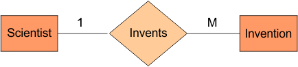
ii. One-to-Many (1:N) Relationship
A One-to-Many (1:N) relationship means that each record in Table A may be related to zero, one, or many records in Table B, but each record in Table B is related to at most one record in Table A.
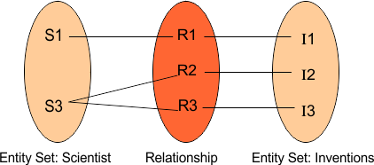
For example, Scientists can invent many inventions, but the invention is done by only one scientist.
The above diagram Can be understood through the following diagram.
Implementation:
Add a foreign key in the “many” side (Employee) that references the “one” side (Department).
Note: A Many-to-One (N:1) relationship is essentially the same as a One-to-Many (1:N) relationship, just viewed from the opposite direction.
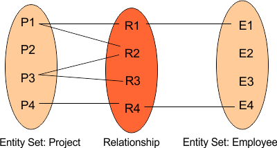
iii. Many-to-Many (M:N) Relationship
A Many-to-Many (M:N) relationship means that each record in Table A may be related to zero, one, or many records in Table B, and each record in Table B may also be related to zero, one, or many records in Table A.
Example:
For example, Projects can be assigned by many employees, and employees can have many projects.
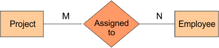
We can represent the above diagram in the following diagram
Implementation
Use a junction table (also called a bridge or associative entity), like Student_Course, with foreign keys referencing both Student_ID and Course_ID.
2) Minimum Cardinality / Modality / Participation
In database design, modality is also known as minimum cardinality or participation, refers to the minimum number of times an entity must engage in a relationship.
While cardinality examines the maximum number of relationships (e.g., 1 or many), modality or participation defines the minimum (e.g., 0 or 1).
There are two main types of modality:
i.) Optional Participation (Minimum = 0)
An entity is not required to participate in a relationship, and some records may not have a related record in the other table.
ER Diagram Notation:
- Shown with a circle (○) near the entity.
Example:
-
Customer ↔ Order
A customer may not place any orders, so participation from Customer in Order is optional.
ii.) Mandatory Participation (Minimum = 1)
An entity must participate in a relationship at least once. That means every record must have a related record.
ER Diagram Notation:
- Shown with a bar (|) near the entity.
Example:
-
Employee ↔ Department
Every employee must belong to a department, so participation from Employee in Department is mandatory.
3) Cardinality + Modality Together
When you combine Cardinality (how many) and Modality (mandatory or optional), you’re defining the full relationship constraints between two entities in an Entity-Relationship Diagram (ERD).
Let’s list all possible combinations of Cardinality and Modality for a specific entity.
| (Cardinality, Modality) | Cardinality | Modality | Meaning |
|---|---|---|---|
| (1, 0) | One | Optional | 0 or 1 relationships |
| (1, 1) | One | Mandatory | Exactly 1 relationship |
| (N, 0) | Many | Optional | 0 or more relationships |
| (N, 1) | Many | Mandatory | 1 or more relationships |
So for Entity A and Entity B, we get 4 × 4 = 16 combinations. All 16 Combinations: A (Cardinality, Modality), B (Cardinality, Modality) are
| # | A (Card, Mod) | B (Card, Mod) | Description |
|---|---|---|---|
| 1 | (1, 0) | (1, 0) | A may relate to 0 or 1 B; B may relate to 0 or 1 A. Optional 1:1. |
| 2 | (1, 0) | (N, 0) | A may relate to 0 or 1B; B may relate to 0 or many As; . Optional 1:N. |
| 3 | (1, 0) | (1, 1) | A optional; B must relate to exactly one A. A may relate to 0 or 1 B. |
| 4 | (1, 0) | (N, 1) | A optional; B must relate to at least one A. |
| 5 | (N, 0) | (1, 0) | A may relate to 0 or more Bs; B may relate to 0 or 1 A. |
| 6 | (N, 0) | (N, 0) | Optional many-to-many. Both sides optional. |
| 7 | (N, 0) | (1, 1) | A optional; B must relate to exactly one A. A may relate to many Bs. |
| 8 | (N, 0) | (N, 1) | A optional; B must relate to at least one A. Many-to-many with required B-side. |
| 9 | (1, 1) | (1, 0) | A must relate to exactly one B; B optional. |
| 10 | (1, 1) | (N, 0) | A must relate to many Bs; B optional. |
| 11 | (1, 1) | (1, 1) | Both must relate to exactly one of the other. Mandatory 1:1. |
| 12 | (1, 1) | (N, 1) | A must relate to many Bs; B must relate to exactly one A. |
| 13 | (N, 1) | (1, 0) | A must relate to at least one B; B optional. |
| 14 | (N, 1) | (N, 0) | A must relate to at least one B; B optional many. |
| 15 | (N, 1) | (1, 1) | A must relate to at least one B; B must relate to exactly one A. |
| 16 | (N, 1) | (N, 1) | Mandatory many-to-many. Each A must relate to at least one B and vice versa. |
4) Degree of Relationship
In Entity-Relationship (ER) modeling, the degree of relationship refers to the number of entity types that participate in a relationship.
Types of Degrees of Relationship
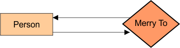
i. Unary Relationship (Degree = 1)
It is also called a recursive relationship. A single entity is related to itself.
Example: one person is married to one person.
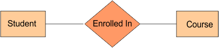
ii. Binary Relationship (Degree = 2)
It involves two different entities. Most common type of relationship in databases.
Example: Student is enrolled in Course.
iii. Ternary Relationship (Degree = 3)
It involves three entities in a single relationship. Cannot be broken into binary relationships without losing meaning.
- Example: A doctor prescribes Medicine to a Patient
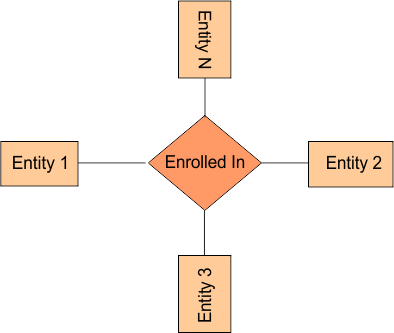
iv. n-ary Relationship (Degree = n)
It involves n entities. Rarely used beyond ternary, as they are complex and often better represented using associative entities.
Example: A Supplier supplies a Part to a Warehouse on a Date.
|
Note:
|
5) Special relationships
Here are some special types of relationships
i) Identifying / Weak Relationship
-
A child entity’s primary key includes the parent’s primary key.
-
The child cannot exist without the parent.
-
Denoted with a solid line in ER diagrams.
Example:
-
Order → OrderItem
-
OrderItem’s primary key includes OrderID (from Order)
-
Notation: The representation of a weak relationship is a double-diamond symbol.
ii) Non-identifying / Strong Relationship
-
The child’s primary key is independent of the parent’s.
-
The child can exist without the parent.
-
Denoted with a dashed line.
Example:
-
Customer → Order
-
Order has CustomerID as a foreign key, but its primary key is just OrderID.
-
Notation: A strong relationship is represented through a diamond symbol, as shown below.

iii. Hierarchical Relationships (Recursive / Tree Structures)
-
A special case of unary (recursive) relationships where one entity is related to itself in a hierarchy (like parent-child).
-
Often used to represent organizational charts, file systems, etc.
Example:
-
Employee supervises another Employee.
-
Creates a tree structure: CEO → Manager → Developer
ER Notation:
-
A single entity with a recursive relationship back to itself, often with roles (e.g., “manager” and “subordinate”).
iv. Associative (Bridge / Junction) Relationships
-
Also called a composite or bridge entity.
-
Used to resolve many-to-many relationships by turning them into two one-to-many relationships.
-
The associative entity often has its own attributes.
Example:
-
Student enrolls in Course → resolve M:N with Enrollment
-
Enrollment is the associative entity.
6) Advanced abstractions
Generalization, Specialization, and Aggregation are abstractions that help model complex real-world relationships more accurately, particularly when entities share attributes or relationships. These concepts enhance basic ER modeling by adding semantic richness to the design.
i. Generalization
Generalization is the process of combining two or more entity sets that share common attributes into a single, higher-level super-entity.
- Key Idea: Bottom-up abstraction. Multiple specific entities become one generalized entity.
- Example: Car, Truck, Motorcycle → all generalized into Vehicle.
- Relationship Type: “is-a” (i.e. A car is a vehicle)
ii. Specialization
Specialization is the process of dividing a higher-level entity into two or more lower-level sub-entities based on distinct characteristics.
- Key Idea: Top-down refinement. One general entity is split into specific types.
- Example: Employee specialized into Manager, Engineer, Intern.
- Relationship Type: “is-a” (i.e. A manager is an employee)
iii. Aggregation
Aggregation is an abstraction that treats a relationship between entities as a higher-level entity itself, allowing it to participate in another relationship.
- Key Idea: Modeling relationships between relationships.
- Example: Employee works on Project, and this relationship is managed by a Department.
- Relationship Type: “has-a” (i.e. A department has a responsibility for an employee working on a project)