


Moore to Mealy Conversion
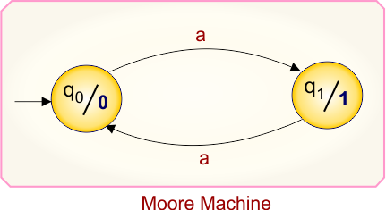
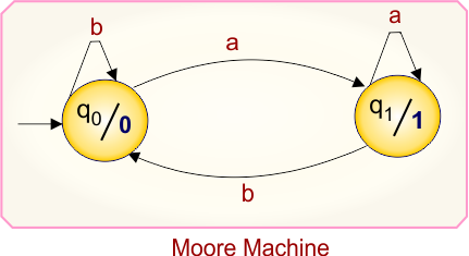
Each Moore Machine is easily converted into its corresponding Mealy Machine. The equivalence of the Moore and Mealy machines means that both machines produce the same output for the same input.
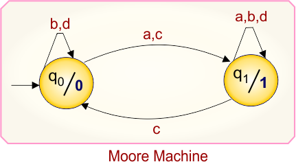
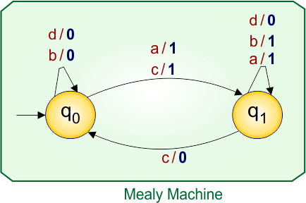
As we know, in the Moore machine, the output is attached to every state symbol, and in the Mealy machine, the output is attached to the input symbol.
Moore to Mealy Conversion Algorithm
Here is the simple rule for Moore to Mealy conversion.
Find the output symbol of each transition from each state. Simply place the output symbol along with the input over the arrow.
The rule begins from an initial state, labeled as “q0,” and continues until it reaches all possible states.
Note: In the Mealy machine, the output on a transition is equal to the output of the next state in the Moore machine.
Moore to Mealy Conversion Working
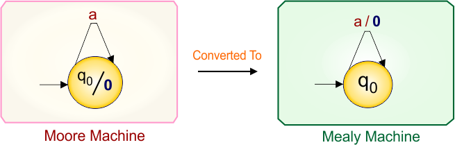
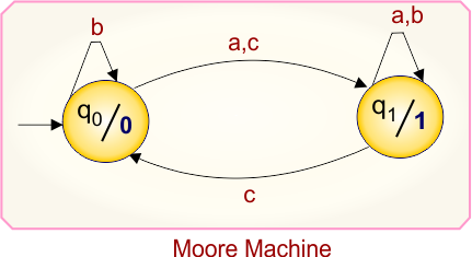
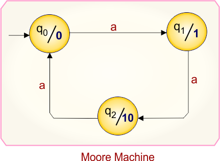
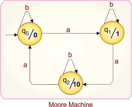
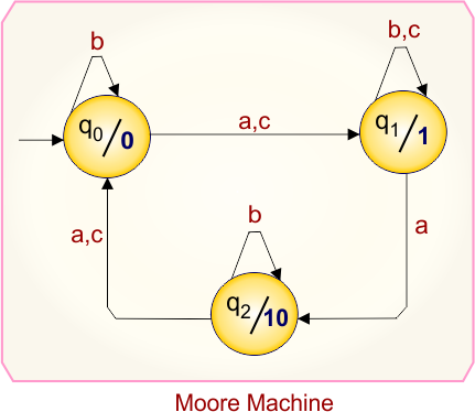
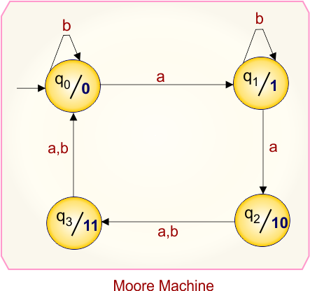
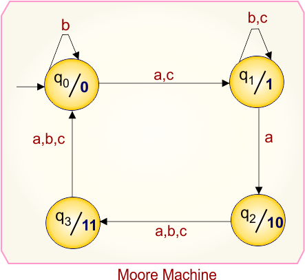
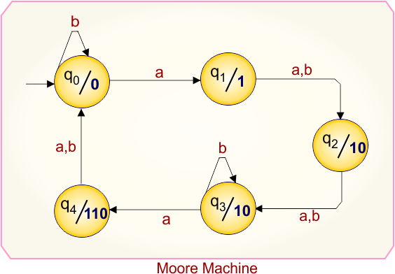
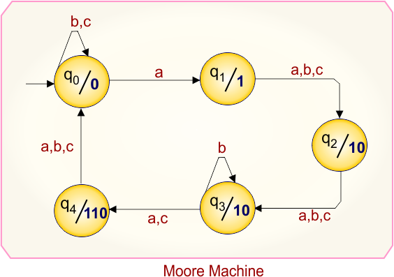
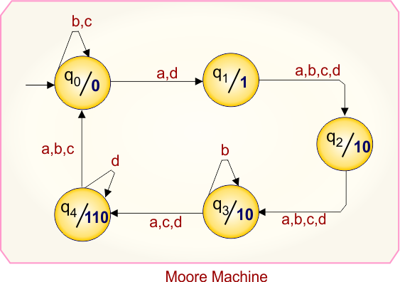
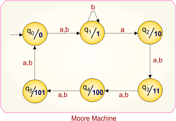
Consider the following Moore Machine, which needs to be converted into a Mealy Machine
Let’s convert the above Moore Machine into the corresponding Mealy Machine.
In Moore Machine
- At state “q0” for input “a”, the transition also goes to the state “q0”, which gives output “0”.
For Mealy Machine conversion,
- Just label output (“0”) with input (“a”) over the arrow for transition as (a/0).
Let us explain various categories of Moore to Mealy conversions
Category 1: Moore to Mealy Conversion Using 1-State
Example 1.1: 1-State, 1-Input Symbol
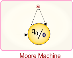
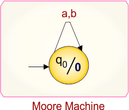
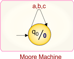
Moore Machine
Here is the Moore Machine, which contains a single state (“q0”) with the output (“0”) and one input symbol (“a”). We will convert it into a corresponding Mealy machine.
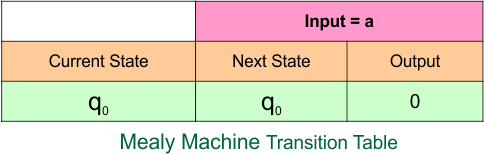
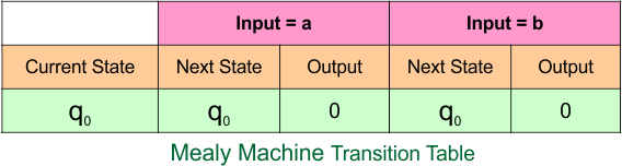
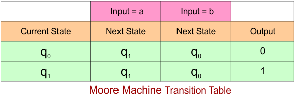
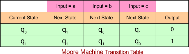
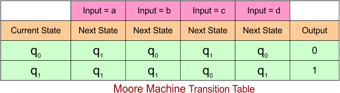
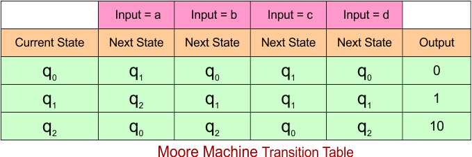
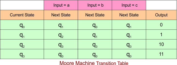
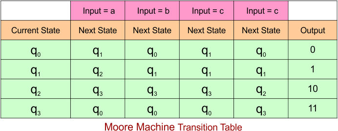
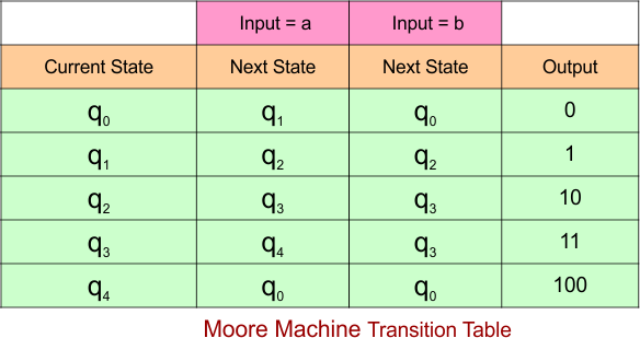
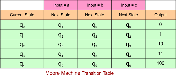
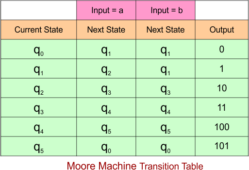
Moore Machine Transition Table
Here is the transition table for the given Moore machine
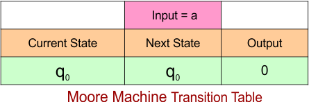
The explanation of the above Mealy Machine transition table is given below
- At the current state “q0”, when the input is “a”, the next state remains “q0” and the output is “0”.
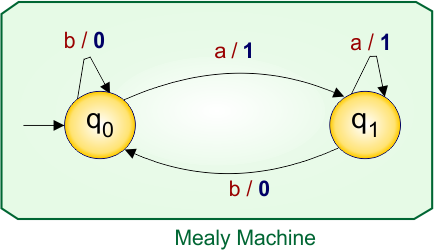
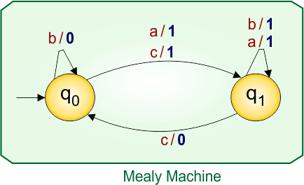
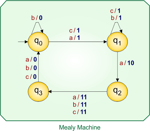
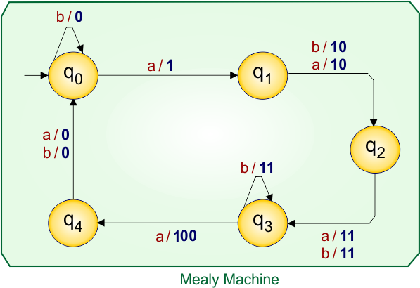
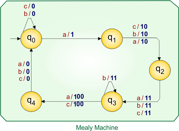
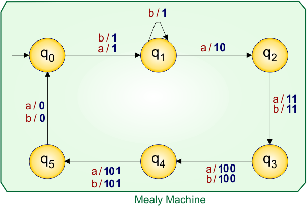
Mealy Machine
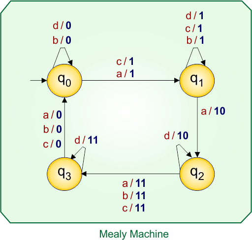
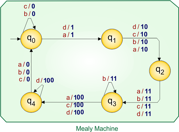
According to the rule of Moore to Mealy conversion, the corresponding Mealy machine is given below,
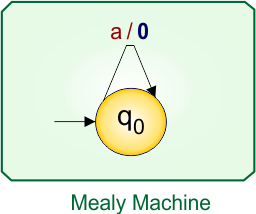
Let’s explain the Moore to Mealy conversion process
At state “q0”:
- For input “a”, the Moore machine moves to state “q0”, and since “q0” gives output “0”, the corresponding Mealy machine transition (over arrow) is written as a/0.
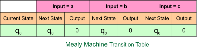
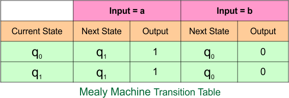
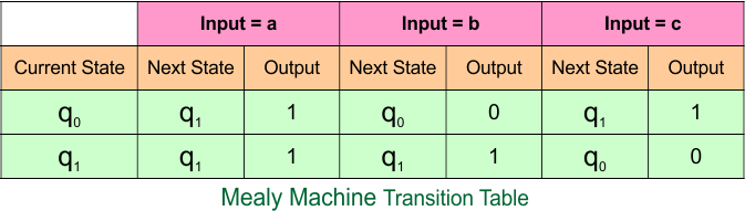
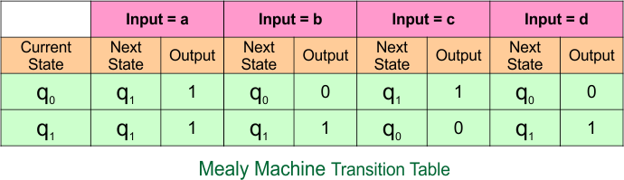
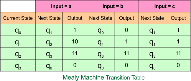
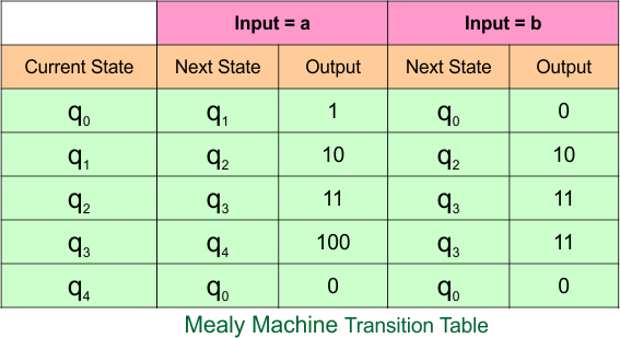
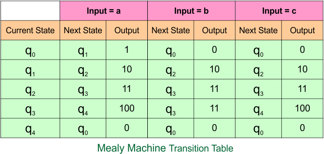
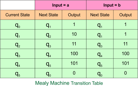
Mealy Machine Transition Table
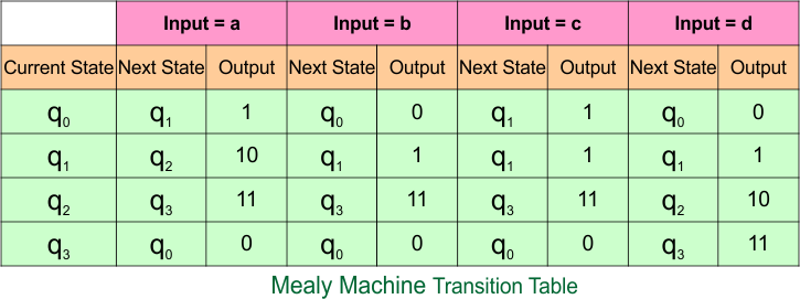
The transition table of the above Mealy machine is given below
The explanation of the above Mealy Machine transition table is given below
- In the current state “q0”, when the input is “a”, the next state remains “q0” and the output is “0”.
Example 1.2: 1-State, 2-Input Symbols
Moore Machine
Here is the Moore Machine, which contains a single state (“q0”) with the output (“0”) and two input symbols (“a”, “b”). We will convert it into a corresponding Mealy machine.
Moore Machine Transition Table
Here is the transition table for the given Moore machine
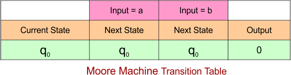
The explanation of the above Mealy Machine transition table is given below
- At the current state “q0”, for both inputs “a” and “b”, the next state remains “q0” and the output is “0”.
Mealy Machine
According to the rule of Moore to Mealy conversion, the corresponding Mealy machine is given below,
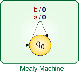
Let’s explain the Moore to Mealy conversion process
At state “q0”:
- For input “a” and “b”, the Moore machine moves to state “q0”, and since “q0” gives output “0”, the corresponding Mealy machine transition (over arrow) is written as a/0 and “b/0”.
Mealy Machine Transition Table
The transition table of the above Mealy machine is given below
The explanation of the above Mealy Machine transition table is given below
- In the current state “q0”, when the input is “a” or “b”, the next state remains “q0” and the output is also “0” in both cases.
Example 1.3: 1-State, 3-Input Symbols
Moore Machine
Here is the Moore Machine, which contains a single state (“q0”) with the output (“0”) and the input symbols (“a”, “b”, “c”). We will convert it into a corresponding Mealy machine.
Moore Machine Transition Table
Here is the transition table for the given Moore machine
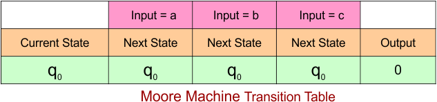
The explanation of the above Mealy Machine transition table is given below
- At the current state “q0”, for all inputs “a”, “b”, and “c”, the next state remains “q0” and the output is “0”.
Mealy Machine
According to the rule of Moore to Mealy conversion, the corresponding Mealy machine is given below,
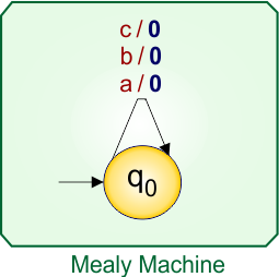
Let’s explain the Moore to Mealy conversion process
At state “q0”:
- For input “a”, “b,” and “c”, the Moore machine moves to state “q0”, and since “q0” gives output “0”, the corresponding Mealy machine transition (over arrow) is written as a/0″, “b/0”, and “c/0”.
Mealy Machine Transition Table
The transition table of the above Mealy machine is given below
The explanation of the above Mealy Machine transition table is given below
- In the current state “q0”, when the input is “a”, “b”, or “c”, the next state remains “q0” and the output is always “0” in all cases.
Example 1.4: 1-State, 4-Input Symbols
Moore Machine
Here is the Moore Machine, which contains a single state (“q0”) with the output (“0”) and all input symbols (“a”, “b”, “c”, “d”). We will convert it into a corresponding Mealy machine.

Moore Machine Transition Table
Here is the transition table for the given Moore machine
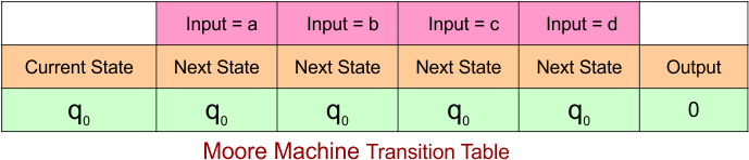
The explanation of the above Mealy Machine transition table is given below
- At the current state “q0”, for all inputs “a”, “b”, “c”, and “d”, the next state remains “q0” and the output is “0”.
Mealy Machine
According to the rule of Moore to Mealy conversion, the corresponding Mealy machine is given below,
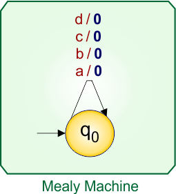
Let’s explain the Moore to Mealy conversion process
At state “q0”:
- For input “a”, “b”, “c”, and “d”, the Moore machine moves to state “q0”, and since “q0” gives output “0”, the corresponding Mealy machine transition (over arrow) is written as “a/0”, “b/0”, “c/0”, and “d/0”.
Mealy Machine Transition Table
The transition table of the above Mealy machine is given below
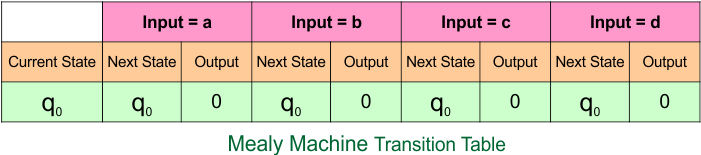
The explanation of the above Mealy Machine transition table is given below
- In the current state “q0”, when the input is “a”, “b”, “c”, or “d”, the next state remains “q0” and the output is always “0” in all cases.
Category 2: Moore to Mealy Conversion Using 2-States
Example 2.1: 2-States, 1-Input Symbol
Moore Machine
Here is the Moore Machine, which contains a two-state (“q0” and “q1”) with outputs (“0” and “1”) and one input symbol (“a”). We will convert it into a corresponding Mealy machine.
Moore Machine Transition Table
Here is the transition table for the given Moore machine
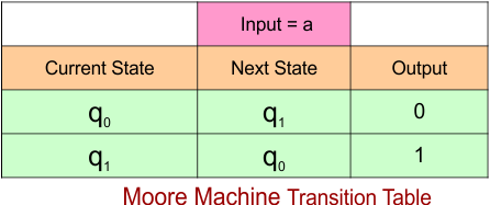
The explanation of the above Mealy Machine transition table is given below
- At the current state “q0”, when the input is “a”, the next state remains “q1” and the output is “0”.
- At the current state “q1”, when the input is “a”, the next state remains “q0” and the output is “1”.
Mealy Machine
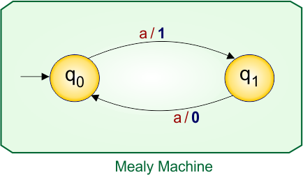
According to the rule of Moore to Mealy conversion, the corresponding Mealy machine is given below,
Let’s explain the Moore to Mealy conversion process
At state “q0”:
- For input “a”, the Moore machine moves to state “q1”, and since “q1” gives output “1”, the corresponding Mealy machine transition (over arrow) is written as a/1.
At state “q1”:
- For input “a”, the Moore machine moves to state “q0”, and since “q0” gives output “0”, the corresponding Mealy machine transition (over arrow) is written as a/0.
Mealy Machine Transition Table
The transition table of the above Mealy machine is given below
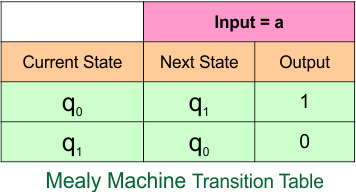
The explanation of the above Mealy Machine transition table is given below
- In the current state “q0”, when the input is “a”, the next state remains “q1” and the output is “1”.
- In the current state “q1”, when the input is “a”, the next state remains “q0” and the output is “0”.
Example 2.2: 2-States, 2-Input Symbol
Moore Machine
Here is the Moore Machine, which contains a two-state (“q0” and “q1”) with outputs (“0” and “1”) and two input symbols (“a” and “b”). We will convert it into a corresponding Mealy machine.
Moore Machine Transition Table
Here is the transition table for the given Moore machine
The explanation of the above Mealy Machine transition table is given below
At the current state “q0”,
- When the input is “a”, the next state remains “q1” and the output is “0”.
- When the input is “b”, the next state remains “q0” and the output is “1”.
At the current state “q1”,
- When the input is “a”, the next state remains “q1” and the output is “0”.
- When the input is “b”, the next state remains “q0” and the output is “0”.
Mealy Machine
According to the rule of Moore to Mealy conversion, the corresponding Mealy machine is given below,
Let’s explain the Moore to Mealy conversion process
At state “q0”:
- For input “a”, the Moore machine moves to state “q1”, and since “q1” gives output “1”, the corresponding Mealy machine transition (over arrow) is written as a/1.
- For input “b”, the Moore machine moves to state “q0”, and since “q0” gives output “0”, the corresponding Mealy machine transition (over arrow) is written as b/0.
At state “q1”:
- For input “a”, the Moore machine moves to state “q1”, and since “q1” gives output “1”, the corresponding Mealy machine transition (over arrow) is written as a/1.
- For input “b”, the Moore machine moves to state “q0”, and since “q0” gives output “0”, the corresponding Mealy machine transition (over arrow) is written as b/0.
Mealy Machine Transition Table
The transition table of the above Mealy machine is given below
The explanation of the above Mealy Machine transition table is given below
At the current state “q0”,
- When the input is “a”, the next state remains “q1” and the output is “1”.
- When the input is “b”, the next state remains “q0” and the output is “0”.
At the current state “q1”,
- When the input is “a”, the next state remains “q1” and the output is “1”.
- When the input is “b”, the next state remains “q0” and the output is “0”.
Example 2.3: 2-States, 3-Input Symbol
Moore Machine
Here is the Moore Machine, which contains a two-state (“q0” and “q1”) with outputs (“0” and “1”) and three input symbols (“a”, “b”, “c”). We will convert it into a corresponding Mealy machine.
Moore Machine Transition Table
Here is the transition table for the given Moore machine
The explanation of the above Mealy Machine transition table is given below
At the current state “q0”,
- When the input is “a”, the next state remains “q1” and the output is “0”.
- When the input is “b”, the next state remains “q0” and the output is “0”.
- When the input is “c”, the next state remains “q1” and the output is “0”.
At the current state “q1”,
- When the input is “a”, the next state remains “q1” and the output is “1”.
- When the input is “b”, the next state remains “q1” and the output is “1”.
- When the input is “c”, the next state remains “q0” and the output is “1”.
Mealy Machine
According to the rule of Moore to Mealy conversion, the corresponding Mealy machine is given below,
Let’s explain the Moore to Mealy conversion process
At state “q0”:
- For input “a”, the Moore machine moves to state “q1”, and since “q1” gives output “1”, the corresponding Mealy machine transition (over arrow) is written as a/1.
- For input “b”, the Moore machine moves to state “q0”, and since “q0” gives output “0”, the corresponding Mealy machine transition (over arrow) is written as b/0.
- For input “c”, the Moore machine moves to state “q1”, and since “q1” gives output “1”, the corresponding Mealy machine transition (over arrow) is written as c/1.
At state “q1”:
- For input “a”, the Moore machine moves to state “q1”, and since “q1” gives output “1”, the corresponding Mealy machine transition (over arrow) is written as a/1.
- For input “b”, the Moore machine moves to state “q1”, and since “q1” gives output “1”, the corresponding Mealy machine transition (over arrow) is written as b/1.
- For input “c”, the Moore machine moves to state “q0”, and since “q0” gives output “0”, the corresponding Mealy machine transition (over arrow) is written as c/0.
Mealy Machine Transition Table
The transition table of the above Mealy machine is given below
The explanation of the above Mealy Machine transition table is given below
At the current state “q0”,
- When the input is “a”, the next state remains “q1” and the output is “1”.
- When the input is “b”, the next state remains “q0” and the output is “0”.
- When the input is “c”, the next state remains “q1” and the output is “1”.
At the current state “q1”,
- When the input is “a”, the next state remains “q1” and the output is “1”.
- When the input is “b”, the next state remains “q1” and the output is “1”.
- When the input is “c”, the next state remains “q0” and the output is “0”.
Example 2.4: 2-States, 4-Input Symbol
Moore Machine
Here is the Moore Machine, which contains a two-state (“q0” and “q1”) with outputs (“0” and “1”) and three input symbols (“a”, “b”, “c”, and “d”). We will convert it into a corresponding Mealy machine.
Moore Machine Transition Table
Here is the transition table for the given Moore machine
The explanation of the above Mealy Machine transition table is given below
At the current state “q0”,
- When the input is “a”, the next state remains “q1” and the output is “0”.
- When the input is “b”, the next state remains “q0” and the output is “0”.
- When the input is “c”, the next state remains “q1” and the output is “0”.
- When the input is “d”, the next state remains “q0” and the output is “0”.
At the current state “q1”,
- When the input is “a”, the next state remains “q1” and the output is “1”.
- When the input is “b”, the next state remains “q1” and the output is “1”.
- When the input is “c”, the next state remains “q0” and the output is “1”.
- When the input is “d”, the next state remains “q1” and the output is “1”.
Mealy Machine
According to the rule of Moore to Mealy conversion, the corresponding Mealy machine is given below,
Let’s explain the Moore to Mealy conversion process
At state “q0”:
- For input “a”, the Moore machine moves to state “q1”, and since “q1” gives output “1”, the corresponding Mealy machine transition (over arrow) is written as a/1.
- For input “b”, the Moore machine moves to state “q0”, and since “q0” gives output “0”, the corresponding Mealy machine transition (over arrow) is written as b/0.
- For input “c”, the Moore machine moves to state “q1”, and since “q1” gives output “1”, the corresponding Mealy machine transition (over arrow) is written as c/1.
- For input “d”, the Moore machine moves to state “q0”, and since “q0” gives output “0”, the corresponding Mealy machine transition (over arrow) is written as d/0.
At state “q1”:
- For input “a”, the Moore machine moves to state “q1”, and since “q1” gives output “1”, the corresponding Mealy machine transition (over arrow) is written as a/1.
- For input “b”, the Moore machine moves to state “q1”, and since “q1” gives output “1”, the corresponding Mealy machine transition (over arrow) is written as b/1.
- For input “c”, the Moore machine moves to state “q0”, and since “q0” gives output “0”, the corresponding Mealy machine transition (over arrow) is written as c/0.
- For input “d”, the Moore machine moves to state “q1”, and since “q1” gives output “1”, the corresponding Mealy machine transition (over arrow) is written as d/1.
Mealy Machine Transition Table
The transition table of the above Mealy machine is given below
The explanation of the above Mealy Machine transition table is given below
At the current state “q0”,
- When the input is “a”, the next state remains “q1” and the output is “1”.
- When the input is “b”, the next state remains “q0” and the output is “0”.
- When the input is “c”, the next state remains “q1” and the output is “1”.
- When the input is “d”, the next state remains “q0” and the output is “0”.
At the current state “q1”,
- When the input is “a”, the next state remains “q1” and the output is “1”.
- When the input is “b”, the next state remains “q1” and the output is “1”.
- When the input is “c”, the next state remains “q0” and the output is “0”.
- When the input is “d”, the next state remains “q1” and the output is “1”.
Category 3: Moore to Mealy Conversion Using 3-States
Example 3.1: 3-States, 1-Input Symbol
Moore Machine
Here is the Moore Machine, which contains a three-state (“q0”, “q1”, and “q2”) with outputs (“0”, “1”, and “10”) and one input symbol (“a”). We will convert it into a corresponding Mealy machine.
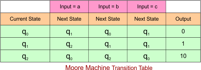
Moore Machine Transition Table
Here is the transition table for the given Moore machine
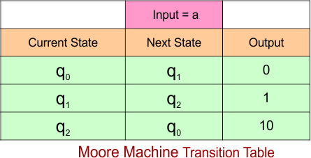
The explanation of the above Mealy Machine transition table is given below
- At the current state “q0”, when the input is “a”, the next state remains “q1” and the output is “0”.
- At the current state “q1”, when the input is “a”, the next state remains “q2” and the output is “1”.
- At the current state “q2”, when the input is “a”, the next state remains “q0” and the output is “10”.
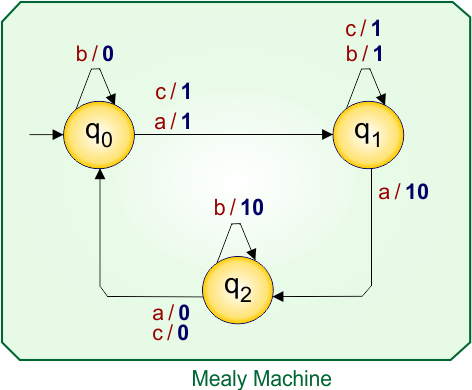
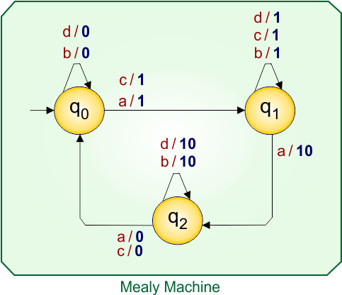
Mealy Machine
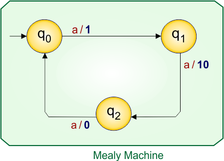
According to the rule of Moore to Mealy conversion, the corresponding Mealy machine is given below,
Let’s explain the Moore to Mealy conversion process
At state “q0”:
- For input “a”, the Moore machine moves to state “q1”, and since “q1” gives output “1”, the corresponding Mealy machine transition (over arrow) is written as a/1.
At state “q1”:
- For input “a”, the Moore machine moves to state “q2”, and since “q2” gives output “10”, the corresponding Mealy machine transition (over arrow) is written as a/10.
At state “q2”:
- For input “a”, the Moore machine moves to state “q0”, and since “q0” gives output “0”, the corresponding Mealy machine transition (over arrow) is written as a/0.
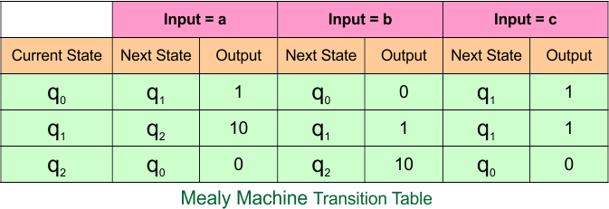
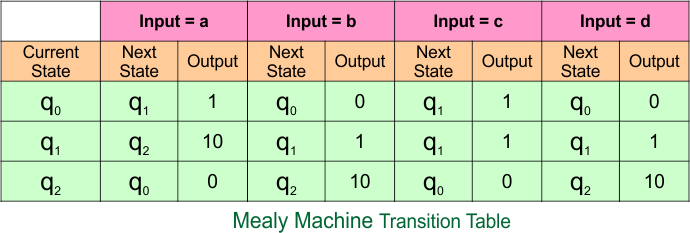
Mealy Machine Transition Table
The transition table of the above Mealy machine is given below
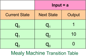
The explanation of the above Mealy Machine transition table is given below
- In the current state “q0”, when the input is “a”, the next state remains “q1” and the output is “1”.
- In the current state “q1”, when the input is “a”, the next state remains “q2” and the output is “10”.
- In the current state “q2”, when the input is “a”, the next state remains “q0” and the output is “0”.
Example 3.2: 3-States, 2-Input Symbol
Moore Machine
Here is the Moore Machine, which contains a three-state (“q0”, “q1”, and “q2”) with outputs (“0”, “1”, and “10”) and two input symbols (“a”, “b”). We will convert it into a corresponding Mealy machine.
Moore Machine Transition Table
Here is the transition table for the given Moore machine
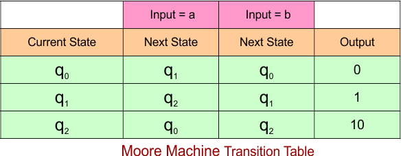
The explanation of the above Mealy Machine transition table is given below
At the current state “q0”,
- When the input is “a”, the next state remains “q1” and the output is “0”.
- When the input is “b”, the next state remains “q0” and the output is “0”.
At the current state “q1”,
- when the input is “a”, the next state remains “q2” and the output is “1”.
- When the input is “b”, the next state remains “q1” and the output is “1”.
At the current state “q2”,
- when the input is “a”, the next state remains “q0” and the output is “10”.
- When the input is “b”, the next state remains “q2” and the output is “10”.
Mealy Machine
According to the rule of Moore to Mealy conversion, the corresponding Mealy machine is given below,
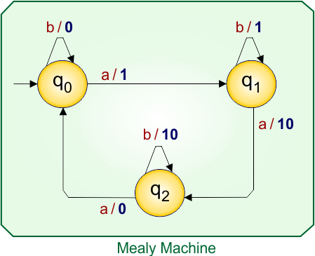
Let’s explain the Moore to Mealy conversion process
At state “q0”:
- For input “a”, the Moore machine moves to state “q1”, and since “q1” gives output “1”, the corresponding Mealy machine transition (over arrow) is written as a/1.
- For input “b”, the Moore machine moves to state “q0”, and since “q0” gives output “0”, the corresponding Mealy machine transition (over arrow) is written as b/0.
At state “q1”:
- For input “a”, the Moore machine moves to state “q2”, and since “q2” gives output “10”, the corresponding Mealy machine transition (over arrow) is written as a/10.
- For input “b”, the Moore machine moves to state “q1”, and since “q1” gives output “1”, the corresponding Mealy machine transition (over arrow) is written as b/1.
At state “q2”:
- For input “a”, the Moore machine moves to state “q0”, and since “q0” gives output “0”, the corresponding Mealy machine transition (over arrow) is written as a/0.
- For input “b”, the Moore machine moves to state “q2”, and since “q2” gives output “10”, the corresponding Mealy machine transition (over arrow) is written as b/10.
Mealy Machine Transition Table
The transition table of the above Mealy machine is given below
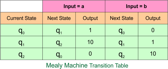
The explanation of the above Mealy Machine transition table is given below
In the current state “q0”,
- when the input is “a”, the next state remains “q1” and the output is “1”.
- When the input is “b”, the next state remains “q0” and the output is “0”.
In the current state “q1”,
- when the input is “a”, the next state remains “q2” and the output is “10”.
- When the input is “b”, the next state remains “q1” and the output is “1”.
In the current state “q2”,
- when the input is “a”, the next state remains “q0” and the output is “0”.
- When the input is “b”, the next state remains “q2” and the output is “10”.
Example 3.3: 3-States, 3-Input Symbol
Moore Machine
Here is the Moore Machine, which contains a three-state (“q0”, “q1”, and “q2”) with outputs (“0”, “1”, and “10”) and three input symbols (“a”, “b”, and “c”). We will convert it into a corresponding Mealy machine.
Moore Machine Transition Table
Here is the transition table for the given Moore machine
The explanation of the above Mealy Machine transition table is given below
At the current state “q0”,
- When the input is “a”, the next state remains “q1” and the output is “0”.
- When the input is “b”, the next state remains “q0” and the output is “0”.
- When the input is “c”, the next state remains “q1” and the output is “0”.
At the current state “q1”,
- when the input is “a”, the next state remains “q2” and the output is “1”.
- When the input is “b”, the next state remains “q1” and the output is “1”.
- When the input is “c”, the next state remains “q1” and the output is “1”.
At the current state “q2”,
- when the input is “a”, the next state remains “q0” and the output is “10”.
- When the input is “b”, the next state remains “q2” and the output is “10”.
- When the input is “c”, the next state remains “q0” and the output is “10”.
Mealy Machine
According to the rule of Moore to Mealy conversion, the corresponding Mealy machine is given below,
Let’s explain the Moore to Mealy conversion process
At state “q0”:
- For input “a”, the Moore machine moves to state “q1”, and since “q1” gives output “1”, the corresponding Mealy machine transition (over arrow) is written as a/1.
- For input “b”, the Moore machine moves to state “q0”, and since “q0” gives output “0”, the corresponding Mealy machine transition (over arrow) is written as b/0.
- For input “c”, the Moore machine moves to state “q1”, and since “q1” gives output “1”, the corresponding Mealy machine transition (over arrow) is written as c/1.
At state “q1”:
- For input “a”, the Moore machine moves to state “q2”, and since “q2” gives output “10”, the corresponding Mealy machine transition (over arrow) is written as a/10.
- For input “b”, the Moore machine moves to state “q1”, and since “q1” gives output “1”, the corresponding Mealy machine transition (over arrow) is written as b/1.
- For input “c”, the Moore machine moves to state “q1”, and since “q1” gives output “1”, the corresponding Mealy machine transition (over arrow) is written as c/1.
At state “q2”:
- For input “a”, the Moore machine moves to state “q0”, and since “q0” gives output “0”, the corresponding Mealy machine transition (over arrow) is written as a/0.
- For input “b”, the Moore machine moves to state “q2”, and since “q2” gives output “10”, the corresponding Mealy machine transition (over arrow) is written as b/10.
- For input “c”, the Moore machine moves to state “q0”, and since “q0” gives output “0”, the corresponding Mealy machine transition (over arrow) is written as c/0.
Mealy Machine Transition Table
The transition table of the above Mealy machine is given below
The explanation of the above Mealy Machine transition table is given below
In the current state “q0”,
- when the input is “a”, the next state remains “q1” and the output is “1”.
- When the input is “b”, the next state remains “q2” and the output is “10”.
- When the input is “c”, the next state remains “q0” and the output is “0”.
In the current state “q1”,
- when the input is “a”, the next state remains “q0” and the output is “0”.
- When the input is “b”, the next state remains “q1” and the output is “1”.
- When the input is “c”, the next state remains “q2” and the output is “10”.
In the current state “q2”,
- when the input is “a”, the next state remains “q1” and the output is “1”.
- When the input is “b”, the next state remains “q1” and the output is “1”.
- When the input is “c”, the next state remains “q0” and the output is “0”.
Example 3.4: 3-States, 4-Input Symbol
Moore Machine
Here is the Moore Machine, which contains a three-state (“q0”, “q1”, and “q2”) with outputs (“0”, “1”, and “10”) and four input symbols (“a”, “b”, “c”, and “d”). We will convert it into a corresponding Mealy machine.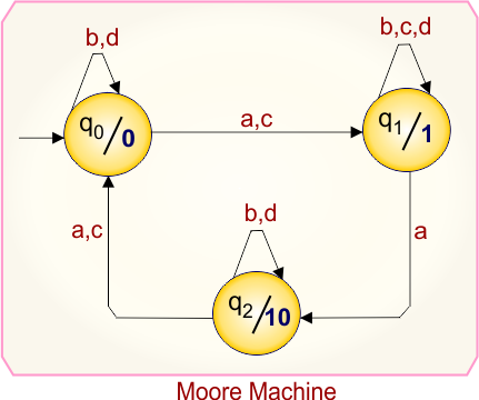
Moore Machine Transition Table
Here is the transition table for the given Moore machine
The explanation of the above Mealy Machine transition table is given below
At the current state “q0”,
- When the input is “a”, the next state remains “q1” and the output is “0”.
- When the input is “b”, the next state remains “q0” and the output is “0”.
- When the input is “c”, the next state remains “q1” and the output is “0”.
- When the input is “d”, the next state remains “q0” and the output is “0”.
At the current state “q1”,
- when the input is “a”, the next state remains “q2” and the output is “1”.
- When the input is “b”, the next state remains “q1” and the output is “1”.
- When the input is “c”, the next state remains “q1” and the output is “1”.
- When the input is “d”, the next state remains “q” and the output is “1”.
At the current state “q2”,
- when the input is “a”, the next state remains “q0” and the output is “10”.
- When the input is “b”, the next state remains “q2” and the output is “10”.
- When the input is “c”, the next state remains “q0” and the output is “10”.
- When the input is “d”, the next state remains “q2” and the output is “10”.
Mealy Machine
According to the rule of Moore to Mealy conversion, the corresponding Mealy machine is given below,
Let’s explain the Moore to Mealy conversion process
At state “q0”:
- For input “a”, the Moore machine moves to state “q1”, and since “q1” gives output “1”, the corresponding Mealy machine transition (over arrow) is written as a/1.
- For input “b”, the Moore machine moves to state “q0”, and since “q0” gives output “0”, the corresponding Mealy machine transition (over arrow) is written as b/0.
- For input “c”, the Moore machine moves to state “q1”, and since “q1” gives output “1”, the corresponding Mealy machine transition (over arrow) is written as c/1.
- For input “d”, the Moore machine moves to state “q1”, and since “q1” gives output “1”, the corresponding Mealy machine transition (over arrow) is written as d/1.
At state “q1”:
- For input “a”, the Moore machine moves to state “q2”, and since “q2” gives output “10”, the corresponding Mealy machine transition (over arrow) is written as a/10.
- For input “b”, the Moore machine moves to state “q1”, and since “q1” gives output “1”, the corresponding Mealy machine transition (over arrow) is written as b/1.
- For input “c”, the Moore machine moves to state “q1”, and since “q1” gives output “1”, the corresponding Mealy machine transition (over arrow) is written as c/1.
- For input “d”, the Moore machine moves to state “q1”, and since “q1” gives output “1”, the corresponding Mealy machine transition (over arrow) is written as d/1.
At state “q2”:
- For input “a”, the Moore machine moves to state “q0”, and since “q0” gives output “0”, the corresponding Mealy machine transition (over arrow) is written as a/0.
- For input “b”, the Moore machine moves to state “q2”, and since “q2” gives output “10”, the corresponding Mealy machine transition (over arrow) is written as b/10.
- For input “c”, the Moore machine moves to state “q0”, and since “q0” gives output “0”, the corresponding Mealy machine transition (over arrow) is written as c/0.
- For input “d”, the Moore machine moves to state “q0”, and since “q0” gives output “0”, the corresponding Mealy machine transition (over arrow) is written as d/0.
Mealy Machine Transition Table
The transition table of the above Mealy machine is given below
The explanation of the above Mealy Machine transition table is given below
In the current state “q0”,
- when the input is “a”, the next state remains “q1” and the output is “1”.
- When the input is “b”, the next state remains “q0” and the output is “0”.
- When the input is “c”, the next state remains “q1” and the output is “1”.
- When the input is “d”, the next state remains “q0” and the output is “0”.
In the current state “q1”,
- when the input is “a”, the next state remains “q2” and the output is “10”.
- When the input is “b”, the next state remains “q1” and the output is “1”.
- When the input is “c”, the next state remains “q1” and the output is “1”.
- When the input is “d”, the next state remains “q1” and the output is “1”.
In the current state “q2”,
- when the input is “a”, the next state remains “q0” and the output is “0”.
- When the input is “b”, the next state remains “q2” and the output is “10”.
- When the input is “c”, the next state remains “q0” and the output is “0”.
- When the input is “d”, the next state remains “q2” and the output is “10”.
Category 4: Moore to Mealy Conversion Using 4-States
Example 4.1: 4-States, 1-Input Symbol
Moore Machine
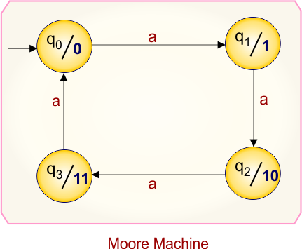
Here is the Moore Machine, which contains a four-state (“q0”, “q1”, “q2”, and “q3”) and outputs (“0”, “1”, “10”, and “11”) and one input symbol (“a”). We will convert it into a corresponding Mealy machine.
Moore Machine Transition Table
Here is the transition table for the given Moore machine
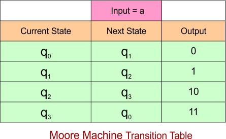
The explanation of the above Mealy Machine transition table is given below
- At the current state “q0”, when the input is “a”, the next state remains “q1” and the output is “0”.
- At the current state “q1”, when the input is “a”, the next state remains “q2” and the output is “1”.
- At the current state “q2”, when the input is “a”, the next state remains “q3” and the output is “10”.
- At the current state “q3”, when the input is “a”, the next state remains “q0” and the output is “11”.
Mealy Machine
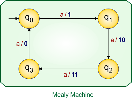
According to the rule of Moore to Mealy conversion, the corresponding Mealy machine is given below,
Let’s explain the Moore to Mealy conversion process
At state “q0”:
- For input “a”, the Moore machine moves to state “q1”, and since “q1” gives output “1”, the corresponding Mealy machine transition (over arrow) is written as a/1.
At state “q1”:
- For input “a”, the Moore machine moves to state “q2”, and since “q2” gives output “10”, the corresponding Mealy machine transition (over arrow) is written as a/10.
At state “q2”:
- For input “a”, the Moore machine moves to state “q3”, and since “q3” gives output “11”, the corresponding Mealy machine transition (over arrow) is written as a/11.
At state “q3”:
- For input “a”, the Moore machine moves to state “q0”, and since “q0” gives output “0”, the corresponding Mealy machine transition (over arrow) is written as a/0.
Mealy Machine Transition Table
The transition table of the above Mealy machine is given below
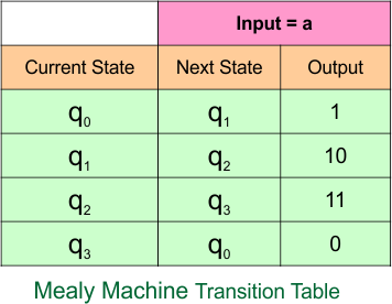
The explanation of the above Mealy Machine transition table is given below
- In the current state “q0”, when the input is “a”, the next state remains “q1” and the output is “1”.
- In the current state “q1”, when the input is “a”, the next state remains “q2” and the output is “10”.
- In the current state “q2”, when the input is “a”, the next state remains “q3” and the output is “11”.
- In the current state “q3”, when the input is “a”, the next state remains “q0” and the output is “0”.
Example 4.2: 4-States, 2-Input Symbol
Moore Machine
Here is the Moore Machine, which contains a four-state (“q0”, “q1”, “q2”, and “q3”) with outputs (“0”, “1”, “10”, and “11”) and two input symbols (“a”, “b”). We will convert it into a corresponding Mealy machine.
Moore Machine Transition Table
Here is the transition table for the given Moore machine
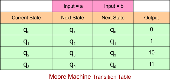
The explanation of the above Mealy Machine transition table is given below
At the current state “q0”,
- When the input is “a”, the next state remains “q1” and the output is “0”.
- When the input is “b”, the next state remains “q0” and the output is “0”.
At the current state “q1”,
- when the input is “a”, the next state remains “q2” and the output is “1”.
- When the input is “b”, the next state remains “q1” and the output is “1”.
At the current state “q2”,
- when the input is “a”, the next state remains “q3” and the output is “10”.
- When the input is “b”, the next state remains “q3” and the output is “10”.
At the current state “q3”,
- when the input is “a”, the next state remains “q0” and the output is “11”.
- When the input is “b”, the next state remains “q0” and the output is “11”.
Mealy Machine
According to the rule of Moore to Mealy conversion, the corresponding Mealy machine is given below,
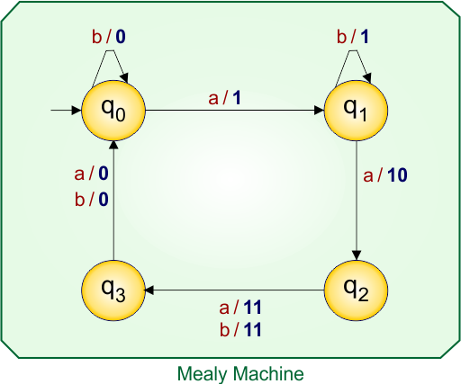
Let’s explain the Moore to Mealy conversion process
At state “q0”:
- For input “a”, the Moore machine moves to state “q1”, and since “q1” gives output “1”, the corresponding Mealy machine transition (over arrow) is written as a/1.
- For input “b”, the Moore machine moves to state “q0”, and since “q0” gives output “0”, the corresponding Mealy machine transition (over arrow) is written as b/0.
At state “q1”:
- For input “a”, the Moore machine moves to state “q2”, and since “q2” gives output “10”, the corresponding Mealy machine transition (over arrow) is written as a/10.
- For input “b”, the Moore machine moves to state “q1”, and since “q1” gives output “1”, the corresponding Mealy machine transition (over arrow) is written as b/1.
At state “q2”:
- For input “a”, the Moore machine moves to state “q3”, and since “q3” gives output “11”, the corresponding Mealy machine transition (over arrow) is written as a/11.
- For input “b”, the Moore machine moves to state “q3”, and since “q3” gives output “11”, the corresponding Mealy machine transition (over arrow) is written as b/11.
At state “q3”:
- For input “a”, the Moore machine moves to state “q0”, and since “q0” gives output “0”, the corresponding Mealy machine transition (over arrow) is written as a/0.
- For input “b”, the Moore machine moves to state “q0”, and since “q0” gives output “0”, the corresponding Mealy machine transition (over arrow) is written as b/0.
Mealy Machine Transition Table
The transition table of the above Mealy machine is given below
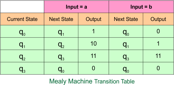
The explanation of the above Mealy Machine transition table is given below
In the current state “q0”,
- when the input is “a”, the next state remains “q1” and the output is “1”.
- When the input is “b”, the next state remains “q0” and the output is “0”.
In the current state “q1”,
- when the input is “a”, the next state remains “q2” and the output is “10”.
- When the input is “b”, the next state remains “q1” and the output is “1”.
In the current state “q2”,
- when the input is “a”, the next state remains “q3” and the output is “11”.
- When the input is “b”, the next state remains “q3” and the output is “11”.
In the current state “q3”,
- when the input is “a”, the next state remains “q0” and the output is “0”.
- When the input is “b”, the next state remains “q0” and the output is “0”.
Example 4.3: 4-States, 3-Input Symbol
Moore Machine
Here is the Moore Machine, which contains a four-state (“q0”, “q1”, “q2”, and “q3”) with outputs (“0”, “1”, “10”, and “11”) and three input symbols (“a”, “b”, “c”). We will convert it into a corresponding Mealy machine.
Moore Machine Transition Table
Here is the transition table for the given Moore machine
The explanation of the above Mealy Machine transition table is given below
At the current state “q0”,
- When the input is “a”, the next state remains “q1” and the output is “0”.
- When the input is “b”, the next state remains “q0” and the output is “0”.
- When the input is “c”, the next state remains “q1” and the output is “0”.
At the current state “q1”,
- when the input is “a”, the next state remains “q2” and the output is “1”.
- When the input is “b”, the next state remains “q1” and the output is “1”.
- When the input is “c”, the next state remains “q1” and the output is “1”.
At the current state “q2”,
- when the input is “a”, the next state remains “q3” and the output is “10”.
- When the input is “b”, the next state remains “q3” and the output is “10”.
- When the input is “c”, the next state remains “q3” and the output is “10”.
At the current state “q3”,
- when the input is “a”, the next state remains “q0” and the output is “11”.
- When the input is “b”, the next state remains “q0” and the output is “11”.
- When the input is “c”, the next state remains “q0” and the output is “11”.
Mealy Machine
According to the rule of Moore to Mealy conversion, the corresponding Mealy machine is given below,
Let’s explain the Moore to Mealy conversion process
At state “q0”:
- For input “a”, the Moore machine moves to state “q1”, and since “q1” gives output “1”, the corresponding Mealy machine transition (over arrow) is written as a/1.
- For input “b”, the Moore machine moves to state “q0”, and since “q0” gives output “0”, the corresponding Mealy machine transition (over arrow) is written as b/0.
- For input “c”, the Moore machine moves to state “q1”, and since “q1” gives output “1”, the corresponding Mealy machine transition (over arrow) is written as c/1.
At state “q1”:
- For input “a”, the Moore machine moves to state “q2”, and since “q2” gives output “10”, the corresponding Mealy machine transition (over arrow) is written as a/10.
- For input “b”, the Moore machine moves to state “q1”, and since “q1” gives output “1”, the corresponding Mealy machine transition (over arrow) is written as b/1.
- For input “c”, the Moore machine moves to state “q1”, and since “q1” gives output “1”, the corresponding Mealy machine transition (over arrow) is written as c/1.
At state “q2”:
- For input “a”, the Moore machine moves to state “q3”, and since “q3” gives output “11”, the corresponding Mealy machine transition (over arrow) is written as a/11.
- For input “b”, the Moore machine moves to state “q3”, and since “q3” gives output “11”, the corresponding Mealy machine transition (over arrow) is written as b/11.
- For input “c”, the Moore machine moves to state “q3”, and since “q3” gives output “11”, the corresponding Mealy machine transition (over arrow) is written as c/11.
At state “q3”:
- For input “a”, the Moore machine moves to state “q0”, and since “q0” gives output “0”, the corresponding Mealy machine transition (over arrow) is written as a/0.
- For input “b”, the Moore machine moves to state “q0”, and since “q0” gives output “0”, the corresponding Mealy machine transition (over arrow) is written as b/0.
- For input “c”, the Moore machine moves to state “q0”, and since “q0” gives output “0”, the corresponding Mealy machine transition (over arrow) is written as c/0.
Mealy Machine Transition Table
The transition table of the above Mealy machine is given below
The explanation of the above Mealy Machine transition table is given below
In the current state “q0”,
- when the input is “a”, the next state remains “q1” and the output is “1”.
- When the input is “b”, the next state remains “q0” and the output is “0”.
- When the input is “c”, the next state remains “q1” and the output is “1”.
In the current state “q1”,
- when the input is “a”, the next state remains “q2” and the output is “10”.
- When the input is “b”, the next state remains “q1” and the output is “1”.
- When the input is “c”, the next state remains “q1” and the output is “1”.
In the current state “q2”,
- when the input is “a”, the next state remains “q3” and the output is “11”.
- When the input is “b”, the next state remains “q3” and the output is “11”.
- When the input is “c”, the next state remains “q3” and the output is “11”.
In the current state “q3”,
- when the input is “a”, the next state remains “q0” and the output is “0”.
- When the input is “b”, the next state remains “q0” and the output is “0”.
- When the input is “c”, the next state remains “q0” and the output is “0”.
Example 4.4: 4-States, 4-Input Symbol
Moore Machine
Here is the Moore Machine, which contains a four-state (“q0”, “q1”, “q2”, and “q3”) with outputs (“0”, “1”, “10”, and “11”) and four input symbols (“a”, “b”, “c”, “d”). We will convert it into a corresponding Mealy machine.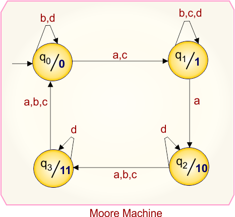
Moore Machine Transition Table
Here is the transition table for the given Moore machine
The explanation of the above Mealy Machine transition table is given below
At the current state “q0”,
- When the input is “a”, the next state remains “q1” and the output is “0”.
- When the input is “b”, the next state remains “q0” and the output is “0”.
- When the input is “c”, the next state remains “q1” and the output is “0”.
- When the input is “d”, the next state remains “q1” and the output is “0”.
At the current state “q1”,
- when the input is “a”, the next state remains “q2” and the output is “1”.
- When the input is “b”, the next state remains “q1” and the output is “1”.
- When the input is “c”, the next state remains “q1” and the output is “1”.
- When the input is “d”, the next state remains “q1” and the output is “1”.
At the current state “q2”,
- when the input is “a”, the next state remains “q3” and the output is “10”.
- When the input is “b”, the next state remains “q3” and the output is “10”.
- When the input is “c”, the next state remains “q3” and the output is “10”.
- When the input is “d”, the next state remains “q2” and the output is “10”.
At the current state “q3”,
- when the input is “a”, the next state remains “q0” and the output is “11”.
- When the input is “b”, the next state remains “q0” and the output is “11”.
- When the input is “c”, the next state remains “q0” and the output is “11”.
- When the input is “d”, the next state remains “q3” and the output is “11”.
Mealy Machine
According to the rule of Moore to Mealy conversion, the corresponding Mealy machine is given below,
Let’s explain the Moore to Mealy conversion process
At state “q0”:
- For input “a”, the Moore machine moves to state “q1”, and since “q1” gives output “1”, the corresponding Mealy machine transition (over arrow) is written as a/1.
- For input “b”, the Moore machine moves to state “q0”, and since “q0” gives output “0”, the corresponding Mealy machine transition (over arrow) is written as b/0.
- For input “c”, the Moore machine moves to state “q1”, and since “q1” gives output “1”, the corresponding Mealy machine transition (over arrow) is written as c/1.
- For input “d”, the Moore machine moves to state “q0”, and since “q0” gives output “0”, the corresponding Mealy machine transition (over arrow) is written as d/0.
At state “q1”:
- For input “a”, the Moore machine moves to state “q2”, and since “q2” gives output “10”, the corresponding Mealy machine transition (over arrow) is written as a/10.
- For input “b”, the Moore machine moves to state “q1”, and since “q1” gives output “1”, the corresponding Mealy machine transition (over arrow) is written as b/1.
- For input “c”, the Moore machine moves to state “q1”, and since “q1” gives output “1”, the corresponding Mealy machine transition (over arrow) is written as c/1.
- For input “d”, the Moore machine moves to state “q1”, and since “q1” gives output “1”, the corresponding Mealy machine transition (over arrow) is written as d/1.
At state “q2”:
- For input “a”, the Moore machine moves to state “q3”, and since “q3” gives output “11”, the corresponding Mealy machine transition (over arrow) is written as a/11.
- For input “b”, the Moore machine moves to state “q3”, and since “q3” gives output “11”, the corresponding Mealy machine transition (over arrow) is written as b/11.
- For input “c”, the Moore machine moves to state “q3”, and since “q3” gives output “11”, the corresponding Mealy machine transition (over arrow) is written as c/11.
- For input “d”, the Moore machine moves to state “q2”, and since “q2” gives output “10”, the corresponding Mealy machine transition (over arrow) is written as d/10.
At state “q3”:
- For input “a”, the Moore machine moves to state “q0”, and since “q0” gives output “0”, the corresponding Mealy machine transition (over arrow) is written as a/0.
- For input “b”, the Moore machine moves to state “q0”, and since “q0” gives output “0”, the corresponding Mealy machine transition (over arrow) is written as b/0.
- For input “c”, the Moore machine moves to state “q0”, and since “q0” gives output “0”, the corresponding Mealy machine transition (over arrow) is written as c/0.
- For input “d”, the Moore machine moves to state “q3”, and since “q3” gives output “11”, the corresponding Mealy machine transition (over arrow) is written as d/11.
Mealy Machine Transition Table
The transition table of the above Mealy machine is given below
The explanation of the above Mealy Machine transition table is given below
In the current state “q0”,
- when the input is “a”, the next state remains “q1” and the output is “1”.
- When the input is “b”, the next state remains “q0” and the output is “0”.
- When the input is “c”, the next state remains “q1” and the output is “1”.
- When the input is “d”, the next state remains “q0” and the output is “0”.
In the current state “q1”,
- when the input is “a”, the next state remains “q2” and the output is “10”.
- When the input is “b”, the next state remains “q1” and the output is “1”.
- When the input is “c”, the next state remains “q1” and the output is “1”.
- When the input is “d”, the next state remains “q1” and the output is “1”.
In the current state “q2”,
- when the input is “a”, the next state remains “q3” and the output is “11”.
- When the input is “b”, the next state remains “q3” and the output is “11”.
- When the input is “c”, the next state remains “q3” and the output is “11”.
- When the input is “d”, the next state remains “q2” and the output is “10”.
In the current state “q3”,
- when the input is “a”, the next state remains “q0” and the output is “0”.
- When the input is “b”, the next state remains “q0” and the output is “0”.
- When the input is “c”, the next state remains “q0” and the output is “0”.
- When the input is “d”, the next state remains “q2” and the output is “11”.
Category 5: Moore to Mealy Conversion Using 5-States
Example 5.1: 5-States, 1-Input Symbol
Moore Machine
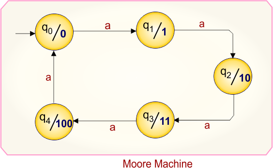
Here is the Moore Machine, which contains a five-state (“q0”, “q1”, “q2”, “q3”, and “q4”) with outputs (“0”, “1”, “10”, “11”, and “100”) and one input symbol (“a”). We will convert it into a corresponding Mealy machine.
Moore Machine Transition Table
Here is the transition table for the given Moore machine
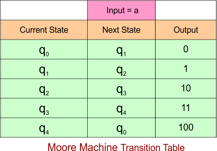
The explanation of the above Mealy Machine transition table is given below
- At the current state “q0”, when the input is “a”, the next state remains “q1” and the output is “0”.
- At the current state “q1”, when the input is “a”, the next state remains “q2” and the output is “1”.
- At the current state “q2”, when the input is “a”, the next state remains “q3” and the output is “10”.
- At the current state “q3”, when the input is “a”, the next state remains “q4” and the output is “11”.
- At the current state “q4”, when the input is “a”, the next state remains “q0” and the output is “100”.
Mealy Machine
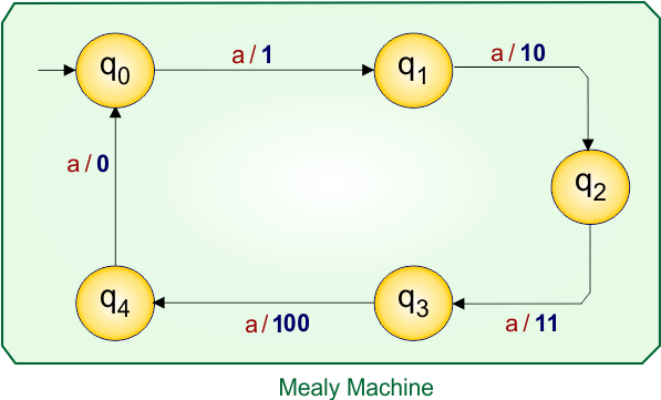
According to the rule of Moore to Mealy conversion, the corresponding Mealy machine is given below,
Let’s explain the Moore to Mealy conversion process
At state “q0”:
- For input “a”, the Moore machine moves to state “q1”, and since “q1” gives output “1”, the corresponding Mealy machine transition (over arrow) is written as a/1.
At state “q1”:
- For input “a”, the Moore machine moves to state “q2”, and since “q2” gives output “10”, the corresponding Mealy machine transition (over arrow) is written as a/10.
At state “q2”:
- For input “a”, the Moore machine moves to state “q3”, and since “q3” gives output “11”, the corresponding Mealy machine transition (over arrow) is written as a/11.
At state “q3”:
- For input “a”, the Moore machine moves to state “q4”, and since “q4” gives output “110”, the corresponding Mealy machine transition (over arrow) is written as a/110.
At state “q4”:
- For input “a”, the Moore machine moves to state “q0”, and since “q0” gives output “0”, the corresponding Mealy machine transition (over arrow) is written as a/0.
Mealy Machine Transition Table
The transition table of the above Mealy machine is given below
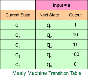
The explanation of the above Mealy Machine transition table is given below
- In the current state “q0”, when the input is “a”, the next state remains “q1” and the output is “1”.
- In the current state “q1”, when the input is “a”, the next state remains “q2” and the output is “10”.
- In the current state “q2”, when the input is “a”, the next state remains “q3” and the output is “11”.
- In the current state “q3”, when the input is “a”, the next state remains “q4” and the output is “0”.
- In the current state “q4”, when the input is “a”, the next state remains “q0” and the output is “0”.
Example 5.2: 5-States, 2-Input Symbol
Moore Machine
Here is the Moore Machine, which contains a five-state (“q0”, “q1”, “q2”, “q3”,, and “q4”) with outputs (“0”, “1”, “10”, “11” and “100”) and two input symbols (“a”, “b”). We will convert it into a corresponding Mealy machine.
Moore Machine Transition Table
Here is the transition table for the given Moore machine
The explanation of the above Mealy Machine transition table is given below
At the current state “q0”,
- When the input is “a”, the next state remains “q1” and the output is “0”.
- When the input is “b”, the next state remains “q0” and the output is “0”.
At the current state “q1”,
- when the input is “a”, the next state remains “q2” and the output is “1”.
- When the input is “b”, the next state remains “q2” and the output is “1”.
At the current state “q2”,
- when the input is “a”, the next state remains “q3” and the output is “10”.
- When the input is “b”, the next state remains “q3” and the output is “10”.
At the current state “q3”,
- when the input is “a”, the next state remains “q4” and the output is “11”.
- When the input is “b”, the next state remains “q3” and the output is “11”.
At the current state “q4”,
- when the input is “a”, the next state remains “q0” and the output is “100”.
- When the input is “b”, the next state remains “q0” and the output is “100”.
Mealy Machine
According to the rule of Moore to Mealy conversion, the corresponding Mealy machine is given below,
Let’s explain the Moore to Mealy conversion process
At state “q0”:
- For input “a”, the Moore machine moves to state “q1”, and since “q1” gives output “1”, the corresponding Mealy machine transition (over arrow) is written as a/1.
- For input “b”, the Moore machine moves to state “q0”, and since “q0” gives output “0”, the corresponding Mealy machine transition (over arrow) is written as b/0.
At state “q1”:
- For input “a”, the Moore machine moves to state “q2”, and since “q2” gives output “10”, the corresponding Mealy machine transition (over arrow) is written as a/10.
- For input “b”, the Moore machine moves to state “q2”, and since “q2” gives output “10”, the corresponding Mealy machine transition (over arrow) is written as b/10.
At state “q2”:
- For input “a”, the Moore machine moves to state “q3”, and since “q3” gives output “11”, the corresponding Mealy machine transition (over arrow) is written as a/11.
- For input “b”, the Moore machine moves to state “q3”, and since “q3” gives output “11”, the corresponding Mealy machine transition (over arrow) is written as b/11.
At state “q3”:
- For input “a”, the Moore machine moves to state “q4”, and since “q4” gives output “100”, the corresponding Mealy machine transition (over arrow) is written as a/100.
- For input “b”, the Moore machine moves to state “q3”, and since “q3” gives output “11”, the corresponding Mealy machine transition (over arrow) is written as b/11.
At state “q4”:
- For input “a”, the Moore machine moves to state “q0”, and since “q0” gives output “0”, the corresponding Mealy machine transition (over arrow) is written as a/0.
- For input “b”, the Moore machine moves to state “q0”, and since “q0” gives output “0”, the corresponding Mealy machine transition (over arrow) is written as b/0.
Mealy Machine Transition Table
The transition table of the above Mealy machine is given below
The explanation of the above Mealy Machine transition table is given below
In the current state “q0”,
- when the input is “a”, the next state remains “q1” and the output is “1”.
- When the input is “b”, the next state remains “q0” and the output is “0”.
In the current state “q1”,
- when the input is “a”, the next state remains “q2” and the output is “10”.
- When the input is “b”, the next state remains “q2” and the output is “10”.
In the current state “q2”,
- when the input is “a”, the next state remains “q3” and the output is “11”.
- When the input is “b”, the next state remains “q3” and the output is “11”.
In the current state “q3”,
- when the input is “a”, the next state remains “q4” and the output is “100”.
- When the input is “b”, the next state remains “q3” and the output is “11”.
In the current state “q4”,
- when the input is “a”, the next state remains “q0” and the output is “0”.
- When the input is “b”, the next state remains “q0” and the output is “0”.
Example 5.3: 5-States, 3-Input Symbol
Moore Machine
Here is the Moore Machine, which contains a five-state (“q0”, “q1”, “q2”, “q3”, and “q4”) with outputs (“0”, “1”, “10”, “11” and “100”) and three input symbols (“a”, “b”, “c”). We will convert it into a corresponding Mealy machine.
Moore Machine Transition Table
Here is the transition table for the given Moore machine
The explanation of the above Mealy Machine transition table is given below
At the current state “q0”,
- When the input is “a”, the next state remains “q1” and the output is “0”.
- When the input is “b”, the next state remains “q0” and the output is “0”.
- When the input is “c”, the next state remains “q0” and the output is “0”.
At the current state “q1”,
- when the input is “a”, the next state remains “q2” and the output is “1”.
- When the input is “b”, the next state remains “q2” and the output is “1”.
- When the input is “c”, the next state remains “q2” and the output is “1”.
At the current state “q2”,
- when the input is “a”, the next state remains “q3” and the output is “10”.
- When the input is “b”, the next state remains “q3” and the output is “10”.
- When the input is “c”, the next state remains “q3” and the output is “10”.
At the current state “q3”,
- when the input is “a”, the next state remains “q4” and the output is “11”.
- When the input is “b”, the next state remains “q3” and the output is “11”.
- When the input is “c”, the next state remains “q4” and the output is “11”.
At the current state “q4”,
- when the input is “a”, the next state remains “q0” and the output is “100”.
- When the input is “b”, the next state remains “q0” and the output is “100”.
- When the input is “c”, the next state remains “q0” and the output is “100”.
Mealy Machine
According to the rule of Moore to Mealy conversion, the corresponding Mealy machine is given below,
Let’s explain the Moore to Mealy conversion process
At state “q0”:
- For input “a”, the Moore machine moves to state “q1”, and since “q1” gives output “1”, the corresponding Mealy machine transition (over arrow) is written as a/1.
- For input “b”, the Moore machine moves to state “q0”, and since “q0” gives output “0”, the corresponding Mealy machine transition (over arrow) is written as b/0.
- For input “c”, the Moore machine moves to state “q0”, and since “q0” gives output “0”, the corresponding Mealy machine transition (over arrow) is written as c/0.
At state “q1”:
- For input “a”, the Moore machine moves to state “q2”, and since “q2” gives output “10”, the corresponding Mealy machine transition (over arrow) is written as a/10.
- For input “b”, the Moore machine moves to state “q2”, and since “q2” gives output “10”, the corresponding Mealy machine transition (over arrow) is written as b/10.
- For input “c”, the Moore machine moves to state “q2”, and since “q2” gives output “10”, the corresponding Mealy machine transition (over arrow) is written as c/10.
At state “q2”:
- For input “a”, the Moore machine moves to state “q3”, and since “q3” gives output “11”, the corresponding Mealy machine transition (over arrow) is written as a/11.
- For input “b”, the Moore machine moves to state “q3”, and since “q3” gives output “11”, the corresponding Mealy machine transition (over arrow) is written as b/11.
- For input “c”, the Moore machine moves to state “q3”, and since “q3” gives output “11”, the corresponding Mealy machine transition (over arrow) is written as c/11.
At state “q3”:
- For input “a”, the Moore machine moves to state “q4”, and since “q4” gives output “100”, the corresponding Mealy machine transition (over arrow) is written as a/100.
- For input “b”, the Moore machine moves to state “q3”, and since “q3” gives output “11”, the corresponding Mealy machine transition (over arrow) is written as b/11.
- For input “c”, the Moore machine moves to state “q4”, and since “q4” gives output “100”, the corresponding Mealy machine transition (over arrow) is written as c/100.
At state “q4”:
- For input “a”, the Moore machine moves to state “q0”, and since “q0” gives output “0”, the corresponding Mealy machine transition (over arrow) is written as a/0.
- For input “b”, the Moore machine moves to state “q0”, and since “q0” gives output “0”, the corresponding Mealy machine transition (over arrow) is written as b/0.
- For input “c”, the Moore machine moves to state “q0”, and since “q0” gives output “0”, the corresponding Mealy machine transition (over arrow) is written as c/0.
Mealy Machine Transition Table
The transition table of the above Mealy machine is given below
The explanation of the above Mealy Machine transition table is given below
In the current state “q0”,
- when the input is “a”, the next state remains “q1” and the output is “1”.
- When the input is “b”, the next state remains “q0” and the output is “0”.
- When the input is “c”, the next state remains “q0” and the output is “0”.
In the current state “q1”,
- when the input is “a”, the next state remains “q2” and the output is “10”.
- When the input is “b”, the next state remains “q2” and the output is “10”.
- When the input is “c”, the next state remains “q2” and the output is “10”.
In the current state “q2”,
- when the input is “a”, the next state remains “q3” and the output is “11”.
- When the input is “b”, the next state remains “q3” and the output is “11”.
- When the input is “c”, the next state remains “q3” and the output is “11”.
In the current state “q3”,
- when the input is “a”, the next state remains “q4” and the output is “100”.
- When the input is “b”, the next state remains “q3” and the output is “11”.
- When the input is “c”, the next state remains “q4” and the output is “100”.
In the current state “q4”,
- when the input is “a”, the next state remains “q0” and the output is “0”.
- When the input is “b”, the next state remains “q0” and the output is “0”.
- When the input is “c”, the next state remains “q0” and the output is “0”.
Example 5.4: 5-States, 4-Input Symbol
Moore Machine
Here is the Moore Machine, which contains a five-state (“q0”, “q1”, “q2”, “q3”, and “q4”) with outputs (“0”, “1”, “10”, “11” and “100”) and four input symbols (“a”, “b”, “c”, and “d”). We will convert it into a corresponding Mealy machine.
Moore Machine Transition Table
Here is the transition table for the given Moore machine
The explanation of the above Mealy Machine transition table is given below
At the current state “q0”,
- When the input is “a”, the next state remains “q1” and the output is “0”.
- When the input is “b”, the next state remains “q0” and the output is “0”.
- When the input is “c”, the next state remains “q0” and the output is “0”.
- When the input is “d”, the next state remains “q1” and the output is “0”.
At the current state “q1”,
- when the input is “a”, the next state remains “q2” and the output is “1”.
- When the input is “b”, the next state remains “q2” and the output is “1”.
- When the input is “c”, the next state remains “q2” and the output is “1”.
- When the input is “d”, the next state remains “q2” and the output is “1”.
At the current state “q2”,
- when the input is “a”, the next state remains “q3” and the output is “10”.
- When the input is “b”, the next state remains “q3” and the output is “10”.
- When the input is “c”, the next state remains “q3” and the output is “10”.
- When the input is “d”, the next state remains “q3” and the output is “10”.
At the current state “q3”,
- when the input is “a”, the next state remains “q4” and the output is “11”.
- When the input is “b”, the next state remains “q3” and the output is “11”.
- When the input is “c”, the next state remains “q4” and the output is “11”.
- When the input is “d”, the next state remains “q4” and the output is “11”.
At the current state “q4”,
- when the input is “a”, the next state remains “q0” and the output is “100”.
- When the input is “b”, the next state remains “q0” and the output is “100”.
- When the input is “c”, the next state remains “q0” and the output is “100”.
- When the input is “d”, the next state remains “q4” and the output is “100”.
Mealy Machine
According to the rule of Moore to Mealy conversion, the corresponding Mealy machine is given below,
Let’s explain the Moore to Mealy conversion process
At state “q0”:
- For input “a”, the Moore machine moves to state “q1”, and since “q1” gives output “1”, the corresponding Mealy machine transition (over arrow) is written as a/1.
- For input “b”, the Moore machine moves to state “q0”, and since “q0” gives output “0”, the corresponding Mealy machine transition (over arrow) is written as b/0.
- For input “c”, the Moore machine moves to state “q0”, and since “q0” gives output “0”, the corresponding Mealy machine transition (over arrow) is written as c/0.
- For input “d”, the Moore machine moves to state “q1”, and since “q1” gives output “1”, the corresponding Mealy machine transition (over arrow) is written as d/1.
At state “q1”:
- For input “a”, the Moore machine moves to state “q2”, and since “q2” gives output “10”, the corresponding Mealy machine transition (over arrow) is written as a/10.
- For input “b”, the Moore machine moves to state “q2”, and since “q2” gives output “10”, the corresponding Mealy machine transition (over arrow) is written as b/10.
- For input “c”, the Moore machine moves to state “q2”, and since “q2” gives output “10”, the corresponding Mealy machine transition (over arrow) is written as c/10.
- For input “d”, the Moore machine moves to state “q2”, and since “q2” gives output “10”, the corresponding Mealy machine transition (over arrow) is written as d/10.
At state “q2”:
- For input “a”, the Moore machine moves to state “q3”, and since “q3” gives output “11”, the corresponding Mealy machine transition (over arrow) is written as a/11.
- For input “b”, the Moore machine moves to state “q3”, and since “q3” gives output “11”, the corresponding Mealy machine transition (over arrow) is written as b/11.
- For input “c”, the Moore machine moves to state “q3”, and since “q3” gives output “11”, the corresponding Mealy machine transition (over arrow) is written as c/11.
- For input “d”, the Moore machine moves to state “q3”, and since “q3” gives output “11”, the corresponding Mealy machine transition (over arrow) is written as d/11.
At state “q3”:
- For input “a”, the Moore machine moves to state “q4”, and since “q4” gives output “100”, the corresponding Mealy machine transition (over arrow) is written as a/100.
- For input “b”, the Moore machine moves to state “q3”, and since “q3” gives output “11”, the corresponding Mealy machine transition (over arrow) is written as b/11.
- For input “c”, the Moore machine moves to state “q4”, and since “q4” gives output “100”, the corresponding Mealy machine transition (over arrow) is written as c/100.
- For input “d”, the Moore machine moves to state “q4”, and since “q4” gives output “100”, the corresponding Mealy machine transition (over arrow) is written as d/100.
At state “q4”:
- For input “a”, the Moore machine moves to state “q0”, and since “q0” gives output “0”, the corresponding Mealy machine transition (over arrow) is written as a/0.
- For input “b”, the Moore machine moves to state “q0”, and since “q0” gives output “0”, the corresponding Mealy machine transition (over arrow) is written as b/0.
- For input “c”, the Moore machine moves to state “q0”, and since “q0” gives output “0”, the corresponding Mealy machine transition (over arrow) is written as c/0.
- For input “d”, the Moore machine moves to state “q4”, and since “q4” gives output “100”, the corresponding Mealy machine transition (over arrow) is written as d/100.
Mealy Machine Transition Table
The transition table of the above Mealy machine is given below
The explanation of the above Mealy Machine transition table is given below
In the current state “q0”,
- when the input is “a”, the next state remains “q1” and the output is “1”.
- When the input is “b”, the next state remains “q0” and the output is “0”.
- When the input is “c”, the next state remains “q0” and the output is “0”.
- When the input is “d”, the next state remains “q1” and the output is “1”.
In the current state “q1”,
- when the input is “a”, the next state remains “q2” and the output is “10”.
- When the input is “b”, the next state remains “q2” and the output is “10”.
- When the input is “c”, the next state remains “q2” and the output is “10”.
- When the input is “d”, the next state remains “q2” and the output is “10”.
In the current state “q2”,
- when the input is “a”, the next state remains “q3” and the output is “11”.
- When the input is “b”, the next state remains “q3” and the output is “11”.
- When the input is “c”, the next state remains “q3” and the output is “11”.
- When the input is “d”, the next state remains “q3” and the output is “11”.
In the current state “q3”,
- when the input is “a”, the next state remains “q4” and the output is “100”.
- When the input is “b”, the next state remains “q3” and the output is “11”.
- When the input is “c”, the next state remains “q4” and the output is “100”.
- When the input is “d”, the next state remains “q4” and the output is “100”.
In the current state “q4”,
- when the input is “a”, the next state remains “q0” and the output is “0”.
- When the input is “b”, the next state remains “q0” and the output is “0”.
- When the input is “c”, the next state remains “q0” and the output is “0”.
- When the input is “d”, the next state remains “q4” and the output is “0”.
Category 6: Moore to Mealy Conversion Using 6-States
Example 6.1: 6-States, 1-Input Symbol
Moore Machine
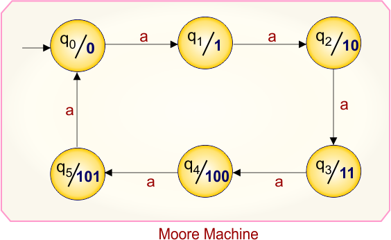
Here is the Moore Machine, which contains a six-state (“q0”, “q1”, “q2”, “q3”, “q4”, and “q5”) with outputs (“0”, “1”, “10”, “11”, “100”, and “101”) and one input symbol (“a”). We will convert it into a corresponding Mealy machine.
Moore Machine Transition Table
Here is the transition table for the given Moore machine
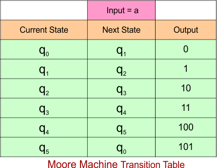
The explanation of the above Mealy Machine transition table is given below
- At the current state “q0”, when the input is “a”, the next state remains “q1” and the output is “0”.
- At the current state “q1”, when the input is “a”, the next state remains “q2” and the output is “1”.
- At the current state “q2”, when the input is “a”, the next state remains “q3” and the output is “10”.
- At the current state “q3”, when the input is “a”, the next state remains “q4” and the output is “11”.
- At the current state “q4”, when the input is “a”, the next state remains “q5” and the output is “100”.
- At the current state “q5”, when the input is “a”, the next state remains “q0” and the output is “101”.
Mealy Machine
According to the rule of Moore to Mealy conversion, the corresponding Mealy machine is given below,
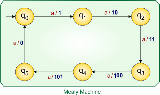
Let’s explain the Moore to Mealy conversion process
At state “q0”:
- For input “a”, the Moore machine moves to state “q1”, and since “q1” gives output “1”, the corresponding Mealy machine transition (over arrow) is written as a/1.
At state “q1”:
- For input “a”, the Moore machine moves to state “q2”, and since “q2” gives output “10”, the corresponding Mealy machine transition (over arrow) is written as a/10.
At state “q2”:
- For input “a”, the Moore machine moves to state “q3”, and since “q3” gives output “11”, the corresponding Mealy machine transition (over arrow) is written as a/11.
At state “q3”:
- For input “a”, the Moore machine moves to state “q4”, and since “q4” gives output “110”, the corresponding Mealy machine transition (over arrow) is written as a/110.
At state “q4”:
- For input “a”, the Moore machine moves to state “q5”, and since “q5” gives output “101”, the corresponding Mealy machine transition (over arrow) is written as a/101.
At state “q5”:
- For input “a”, the Moore machine moves to state “q0”, and since “q0” gives output “0”, the corresponding Mealy machine transition (over arrow) is written as a/0.
Mealy Machine Transition Table
The transition table of the above Mealy machine is given below
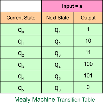
The explanation of the above Mealy Machine transition table is given below
- In the current state “q0”, when the input is “a”, the next state remains “q1” and the output is “1”.
- In the current state “q1”, when the input is “a”, the next state remains “q2” and the output is “10”.
- In the current state “q2”, when the input is “a”, the next state remains “q3” and the output is “11”.
- In the current state “q3”, when the input is “a”, the next state remains “q4” and the output is “100”.
- In the current state “q4”, when the input is “a”, the next state remains “q5” and the output is “101”.
- In the current state “q5”, when the input is “a”, the next state remains “q0” and the output is “0”.
Example 6.2: 6-States, 2-Input Symbol
Moore Machine
Here is the Moore Machine, which contains a six-state (“q0”, “q1”, “q2”, “q3”, “q4” and “q5”) with outputs (“0”, “1”, “10”, “11”, “100” and “101”) and two input symbols (“a”, “b”). We will convert it into a corresponding Mealy machine.
Moore Machine Transition Table
Here is the transition table for the given Moore machine
The explanation of the above Mealy Machine transition table is given below
At the current state “q0”,
- When the input is “a”, the next state remains “q1” and the output is “0”.
- When the input is “b”, the next state remains “q1” and the output is “0”.
At the current state “q1”,
- when the input is “a”, the next state remains “q2” and the output is “1”.
- When the input is “b”, the next state remains “q1” and the output is “1”.
At the current state “q2”,
- when the input is “a”, the next state remains “q3” and the output is “10”.
- When the input is “b”, the next state remains “q3” and the output is “10”.
At the current state “q3”,
- when the input is “a”, the next state remains “q4” and the output is “11”.
- When the input is “b”, the next state remains “q4” and the output is “11”.
At the current state “q4”,
- when the input is “a”, the next state remains “q5” and the output is “100”.
- When the input is “b”, the next state remains “q5” and the output is “100”.
At the current state “q5”,
- when the input is “a”, the next state remains “q0” and the output is “101”.
- When the input is “b”, the next state remains “q0” and the output is “101”.
Mealy Machine
According to the rule of Moore to Mealy conversion, the corresponding Mealy machine is given below,
Let’s explain the Moore to Mealy conversion process
At state “q0”:
- For input “a”, the Moore machine moves to state “q1”, and since “q1” gives output “1”, the corresponding Mealy machine transition (over arrow) is written as a/1.
- For input “b”, the Moore machine moves to state “q1”, and since “q1” gives output “1”, the corresponding Mealy machine transition (over arrow) is written as b/1.
At state “q1”:
- For input “a”, the Moore machine moves to state “q2”, and since “q2” gives output “10”, the corresponding Mealy machine transition (over arrow) is written as a/10.
- For input “b”, the Moore machine moves to state “q1”, and since “q1” gives output “1”, the corresponding Mealy machine transition (over arrow) is written as b/1.
At state “q2”:
- For input “a”, the Moore machine moves to state “q3”, and since “q3” gives output “11”, the corresponding Mealy machine transition (over arrow) is written as a/11.
- For input “b”, the Moore machine moves to state “q3”, and since “q3” gives output “11”, the corresponding Mealy machine transition (over arrow) is written as b/11.
At state “q3”:
- For input “a”, the Moore machine moves to state “q4”, and since “q4” gives output “100”, the corresponding Mealy machine transition (over arrow) is written as a/100.
- For input “b”, the Moore machine moves to state “q4”, and since “q4” gives output “100”, the corresponding Mealy machine transition (over arrow) is written as b/100.
At state “q4”:
- For input “a”, the Moore machine moves to state “q5”, and since “q5” gives output “101”, the corresponding Mealy machine transition (over arrow) is written as a/101.
- For input “b”, the Moore machine moves to state “q5”, and since “q5” gives output “101”, the corresponding Mealy machine transition (over arrow) is written as b/101.
At state “q5”:
- For input “a”, the Moore machine moves to state “q0”, and since “q0” gives output “0”, the corresponding Mealy machine transition (over arrow) is written as a/0.
- For input “b”, the Moore machine moves to state “q0”, and since “q0” gives output “0”, the corresponding Mealy machine transition (over arrow) is written as b/0.
Mealy Machine Transition Table
The transition table of the above Mealy machine is given below
The explanation of the above Mealy Machine transition table is given below
In the current state “q0”,
- when the input is “a”, the next state remains “q1” and the output is “1”.
- When the input is “b”, the next state remains “q1” and the output is “1”.
In the current state “q1”,
- when the input is “a”, the next state remains “q2” and the output is “10”.
- When the input is “b”, the next state remains “q1” and the output is “1”.
In the current state “q2”,
- when the input is “a”, the next state remains “q3” and the output is “11”.
- When the input is “b”, the next state remains “q3” and the output is “11”.
In the current state “q3”,
- when the input is “a”, the next state remains “q4” and the output is “100”.
- When the input is “b”, the next state remains “q4” and the output is “100”.
In the current state “q4”,
- when the input is “a”, the next state remains “q5” and the output is “101”.
- When the input is “b”, the next state remains “q5” and the output is “101”.
In the current state “q5”,
- when the input is “a”, the next state remains “q0” and the output is “0”.
- When the input is “b”, the next state remains “q0” and the output is “0”.
Example 6.3: 6-States, 3-Input Symbol
Moore Machine
Here is the Moore Machine, which contains a six-state (“q0”, “q1”, “q2”, “q3”, “q4” and “q5”) with outputs (“0”, “1”, “10”, “11”, “100” and “101”) and three input symbols (“a”, “b”, “c”). We will convert it into a corresponding Mealy machine.
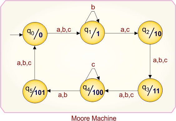
Moore Machine Transition Table
Here is the transition table for the given Moore machine
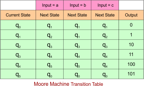
The explanation of the above Mealy Machine transition table is given below
At the current state “q0”,
- When the input is “a”, the next state remains “q1” and the output is “0”.
- When the input is “b”, the next state remains “q1” and the output is “0”.
- When the input is “c”, the next state remains “q1” and the output is “0”.
At the current state “q1”,
- when the input is “a”, the next state remains “q2” and the output is “1”.
- When the input is “b”, the next state remains “q1” and the output is “1”.
- When the input is “c”, the next state remains “q2” and the output is “1”.
At the current state “q2”,
- when the input is “a”, the next state remains “q3” and the output is “10”.
- When the input is “b”, the next state remains “q3” and the output is “10”.
- When the input is “c”, the next state remains “q3” and the output is “10”.
At the current state “q3”,
- when the input is “a”, the next state remains “q4” and the output is “11”.
- When the input is “b”, the next state remains “q4” and the output is “11”.
- When the input is “c”, the next state remains “q4” and the output is “11”.
At the current state “q4”,
- when the input is “a”, the next state remains “q5” and the output is “100”.
- When the input is “b”, the next state remains “q5” and the output is “100”.
- When the input is “c”, the next state remains “q4” and the output is “100”.
At the current state “q5”,
- when the input is “a”, the next state remains “q0” and the output is “101”.
- When the input is “b”, the next state remains “q0” and the output is “101”.
- When the input is “c”, the next state remains “q0” and the output is “101”.
Mealy Machine
According to the rule of Moore to Mealy conversion, the corresponding Mealy machine is given below,
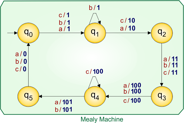
Let’s explain the Moore to Mealy conversion process
At state “q0”:
- For input “a”, the Moore machine moves to state “q1”, and since “q1” gives output “1”, the corresponding Mealy machine transition (over arrow) is written as a/1.
- For input “b”, the Moore machine moves to state “q1”, and since “q1” gives output “1”, the corresponding Mealy machine transition (over arrow) is written as b/1.
- For input “c”, the Moore machine moves to state “q0”, and since “q1” gives output “1”, the corresponding Mealy machine transition (over arrow) is written as c/1.
At state “q1”:
- For input “a”, the Moore machine moves to state “q2”, and since “q2” gives output “10”, the corresponding Mealy machine transition (over arrow) is written as a/10.
- For input “b”, the Moore machine moves to state “q1”, and since “q1” gives output “1”, the corresponding Mealy machine transition (over arrow) is written as b/1.
- For input “c”, the Moore machine moves to state “q2”, and since “q2” gives output “10”, the corresponding Mealy machine transition (over arrow) is written as c/10.
At state “q2”:
- For input “a”, the Moore machine moves to state “q3”, and since “q3” gives output “11”, the corresponding Mealy machine transition (over arrow) is written as a/11.
- For input “b”, the Moore machine moves to state “q3”, and since “q3” gives output “11”, the corresponding Mealy machine transition (over arrow) is written as b/11.
- For input “c”, the Moore machine moves to state “q3”, and since “q3” gives output “11”, the corresponding Mealy machine transition (over arrow) is written as c/11.
At state “q3”:
- For input “a”, the Moore machine moves to state “q4”, and since “q4” gives output “100”, the corresponding Mealy machine transition (over arrow) is written as a/100.
- For input “b”, the Moore machine moves to state “q4”, and since “q4” gives output “100”, the corresponding Mealy machine transition (over arrow) is written as b/100.
- For input “c”, the Moore machine moves to state “q4”, and since “q4” gives output “100”, the corresponding Mealy machine transition (over arrow) is written as c/100.
At state “q4”:
- For input “a”, the Moore machine moves to state “q5”, and since “q5” gives output “101”, the corresponding Mealy machine transition (over arrow) is written as a/101.
- For input “b”, the Moore machine moves to state “q5”, and since “q5” gives output “101”, the corresponding Mealy machine transition (over arrow) is written as b/101.
- For input “c”, the Moore machine moves to state “q4”, and since “q4” gives output “100”, the corresponding Mealy machine transition (over arrow) is written as c/100.
At state “q5”:
- For input “a”, the Moore machine moves to state “q0”, and since “q0” gives output “0”, the corresponding Mealy machine transition (over arrow) is written as a/0.
- For input “b”, the Moore machine moves to state “q0”, and since “q0” gives output “0”, the corresponding Mealy machine transition (over arrow) is written as b/0.
- For input “c”, the Moore machine moves to state “q0”, and since “q0” gives output “0”, the corresponding Mealy machine transition (over arrow) is written as c/0.
Mealy Machine Transition Table
The transition table of the above Mealy machine is given below
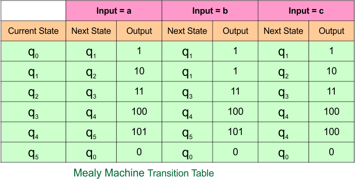
The explanation of the above Mealy Machine transition table is given below
In the current state “q0”,
- when the input is “a”, the next state remains “q1” and the output is “1”.
- When the input is “b”, the next state remains “q1” and the output is “1”.
- When the input is “c”, the next state remains “q1” and the output is “1”.
In the current state “q1”,
- when the input is “a”, the next state remains “q2” and the output is “10”.
- When the input is “b”, the next state remains “q1” and the output is “1”.
- When the input is “c”, the next state remains “q2” and the output is “10”.
In the current state “q2”,
- when the input is “a”, the next state remains “q3” and the output is “11”.
- When the input is “b”, the next state remains “q3” and the output is “11”.
- When the input is “c”, the next state remains “q3” and the output is “11”.
In the current state “q3”,
- when the input is “a”, the next state remains “q4” and the output is “100”.
- When the input is “b”, the next state remains “q4” and the output is “100”.
- When the input is “c”, the next state remains “q4” and the output is “100”.
In the current state “q4”,
- when the input is “a”, the next state remains “q5” and the output is “101”.
- When the input is “b”, the next state remains “q5” and the output is “101”.
- When the input is “c”, the next state remains “q4” and the output is “100”.
In the current state “q5”,
- when the input is “a”, the next state remains “q0” and the output is “0”.
- When the input is “b”, the next state remains “q0” and the output is “0”.
- When the input is “c”, the next state remains “q0” and the output is “0”.
Example 6.4: 6-States, 4-Input Symbol
Moore Machine
Here is the Moore Machine, which contains a six-state (“q0”, “q1”, “q2”, “q3”, “q4” and “q5”) with outputs (“0”, “1”, “10”, “11”, “100” and “101”) and four input symbols (“a”, “b”, “c”, “d”). We will convert it into a corresponding Mealy machine.
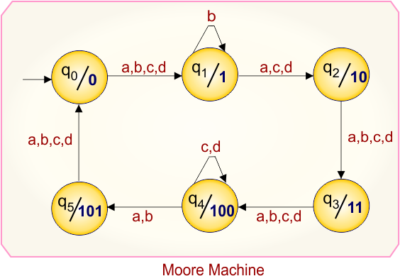
Moore Machine Transition Table
Here is the transition table for the given Moore machine
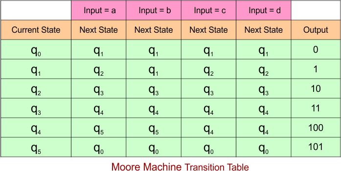
The explanation of the above Mealy Machine transition table is given below
At the current state “q0”,
- When the input is “a”, the next state remains “q1” and the output is “0”.
- When the input is “b”, the next state remains “q1” and the output is “0”.
- When the input is “c”, the next state remains “q1” and the output is “0”.
- When the input is “d”, the next state remains “q1” and the output is “0”.
At the current state “q1”,
- when the input is “a”, the next state remains “q2” and the output is “1”.
- When the input is “b”, the next state remains “q1” and the output is “1”.
- When the input is “c”, the next state remains “q2” and the output is “1”.
- When the input is “d”, the next state remains “q2” and the output is “1”.
At the current state “q2”,
- when the input is “a”, the next state remains “q3” and the output is “10”.
- When the input is “b”, the next state remains “q3” and the output is “10”.
- When the input is “c”, the next state remains “q3” and the output is “10”.
- When the input is “d”, the next state remains “q3” and the output is “10”.
At the current state “q3”,
- when the input is “a”, the next state remains “q4” and the output is “11”.
- When the input is “b”, the next state remains “q4” and the output is “11”.
- When the input is “c”, the next state remains “q4” and the output is “11”.
- When the input is “d”, the next state remains “q4” and the output is “11”.
At the current state “q4”,
- when the input is “a”, the next state remains “q5” and the output is “100”.
- When the input is “b”, the next state remains “q5” and the output is “100”.
- When the input is “c”, the next state remains “q4” and the output is “100”.
- When the input is “d”, the next state remains “q4” and the output is “100”.
At the current state “q5”,
- when the input is “a”, the next state remains “q0” and the output is “101”.
- When the input is “b”, the next state remains “q0” and the output is “101”.
- When the input is “c”, the next state remains “q0” and the output is “101”.
- When the input is “d”, the next state remains “q0” and the output is “101”.
Mealy Machine
According to the rule of Moore to Mealy conversion, the corresponding Mealy machine is given below,
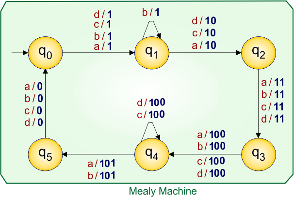
Let’s explain the Moore to Mealy conversion process
At state “q0”:
- For input “a”, the Moore machine moves to state “q1”, and since “q1” gives output “1”, the corresponding Mealy machine transition (over arrow) is written as a/1.
- For input “b”, the Moore machine moves to state “q1”, and since “q1” gives output “1”, the corresponding Mealy machine transition (over arrow) is written as b/1.
- For input “c”, the Moore machine moves to state “q0”, and since “q1” gives output “1”, the corresponding Mealy machine transition (over arrow) is written as c/1.
- For input “d”, the Moore machine moves to state “q0”, and since “q1” gives output “1”, the corresponding Mealy machine transition (over arrow) is written as d/1.
At state “q1”:
- For input “a”, the Moore machine moves to state “q2”, and since “q2” gives output “10”, the corresponding Mealy machine transition (over arrow) is written as a/10.
- For input “b”, the Moore machine moves to state “q1”, and since “q1” gives output “1”, the corresponding Mealy machine transition (over arrow) is written as b/1.
- For input “c”, the Moore machine moves to state “q2”, and since “q2” gives output “10”, the corresponding Mealy machine transition (over arrow) is written as c/10.
- For input “d”, the Moore machine moves to state “q2”, and since “q2” gives output “10”, the corresponding Mealy machine transition (over arrow) is written as d/10.
At state “q2”:
- For input “a”, the Moore machine moves to state “q3”, and since “q3” gives output “11”, the corresponding Mealy machine transition (over arrow) is written as a/11.
- For input “b”, the Moore machine moves to state “q3”, and since “q3” gives output “11”, the corresponding Mealy machine transition (over arrow) is written as b/11.
- For input “c”, the Moore machine moves to state “q3”, and since “q3” gives output “11”, the corresponding Mealy machine transition (over arrow) is written as c/11.
- For input “d”, the Moore machine moves to state “q3”, and since “q3” gives output “11”, the corresponding Mealy machine transition (over arrow) is written as d/11.
At state “q3”:
- For input “a”, the Moore machine moves to state “q4”, and since “q4” gives output “100”, the corresponding Mealy machine transition (over arrow) is written as a/100.
- For input “b”, the Moore machine moves to state “q4”, and since “q4” gives output “100”, the corresponding Mealy machine transition (over arrow) is written as b/100.
- For input “c”, the Moore machine moves to state “q4”, and since “q4” gives output “100”, the corresponding Mealy machine transition (over arrow) is written as c/100.
- For input “d”, the Moore machine moves to state “q4”, and since “q4” gives output “100”, the corresponding Mealy machine transition (over arrow) is written as d/100.
At state “q4”:
- For input “a”, the Moore machine moves to state “q5”, and since “q5” gives output “101”, the corresponding Mealy machine transition (over arrow) is written as a/101.
- For input “b”, the Moore machine moves to state “q5”, and since “q5” gives output “101”, the corresponding Mealy machine transition (over arrow) is written as b/101.
- For input “c”, the Moore machine moves to state “q4”, and since “q4” gives output “100”, the corresponding Mealy machine transition (over arrow) is written as c/100.
- For input “d”, the Moore machine moves to state “q4”, and since “q4” gives output “100”, the corresponding Mealy machine transition (over arrow) is written as d/100.
At state “q5”:
- For input “a”, the Moore machine moves to state “q0”, and since “q0” gives output “0”, the corresponding Mealy machine transition (over arrow) is written as a/0.
- For input “b”, the Moore machine moves to state “q0”, and since “q0” gives output “0”, the corresponding Mealy machine transition (over arrow) is written as b/0.
- For input “c”, the Moore machine moves to state “q0”, and since “q0” gives output “0”, the corresponding Mealy machine transition (over arrow) is written as c/0.
- For input “d”, the Moore machine moves to state “q0”, and since “q0” gives output “0”, the corresponding Mealy machine transition (over arrow) is written as d/0.
Mealy Machine Transition Table
The transition table of the above Mealy machine is given below
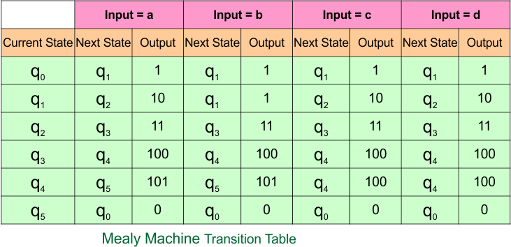
The explanation of the above Mealy Machine transition table is given below
In the current state “q0”,
- when the input is “a”, the next state remains “q1” and the output is “1”.
- When the input is “b”, the next state remains “q1” and the output is “1”.
- When the input is “c”, the next state remains “q1” and the output is “1”.
- When the input is “d”, the next state remains “q1” and the output is “1”.
In the current state “q1”,
- when the input is “a”, the next state remains “q2” and the output is “10”.
- When the input is “b”, the next state remains “q1” and the output is “1”.
- When the input is “c”, the next state remains “q2” and the output is “10”.
- When the input is “d”, the next state remains “q2” and the output is “10”.
In the current state “q2”,
- when the input is “a”, the next state remains “q3” and the output is “11”.
- When the input is “b”, the next state remains “q3” and the output is “11”.
- When the input is “c”, the next state remains “q3” and the output is “11”.
- When the input is “d”, the next state remains “q3” and the output is “11”.
In the current state “q3”,
- when the input is “a”, the next state remains “q4” and the output is “100”.
- When the input is “b”, the next state remains “q4” and the output is “100”.
- When the input is “c”, the next state remains “q4” and the output is “100”.
- When the input is “d”, the next state remains “q4” and the output is “100”.
In the current state “q4”,
- when the input is “a”, the next state remains “q5” and the output is “101”.
- When the input is “b”, the next state remains “q5” and the output is “101”.
- When the input is “c”, the next state remains “q4” and the output is “100”.
- When the input is “d”, the next state remains “q4” and the output is “100”.
In the current state “q5”,
- when the input is “a”, the next state remains “q0” and the output is “0”.
- When the input is “b”, the next state remains “q0” and the output is “0”.
- When the input is “c”, the next state remains “q0” and the output is “0”.
- When the input is “d”, the next state remains “q0” and the output is “0”.
Category 7: Moore to Mealy Conversion Using 7-States
Example 7.1: 7-States, 1-Input Symbol
Moore Machine
Here is the Moore Machine, which contains a seven-state (“q0”, “q1”, “q2”, “q3”, “q4”, “q5” and “q6”) with outputs (“0”, “1”, “10”, “11”, “100”, “101”, and “110”) and one input symbol (“a”). We will convert it into a corresponding Mealy machine.
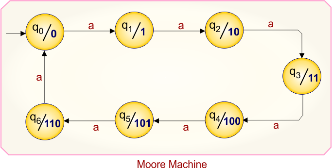
Moore Machine Transition Table
Here is the transition table for the given Moore machine
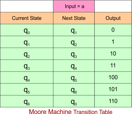
The explanation of the above Mealy Machine transition table is given below
- At the current state “q0”, when the input is “a”, the next state remains “q1” and the output is “0”.
- At the current state “q1”, when the input is “a”, the next state remains “q2” and the output is “1”.
- At the current state “q2”, when the input is “a”, the next state remains “q3” and the output is “10”.
- At the current state “q3”, when the input is “a”, the next state remains “q4” and the output is “11”.
- At the current state “q4”, when the input is “a”, the next state remains “q5” and the output is “100”.
- At the current state “q5”, when the input is “a”, the next state remains “q6” and the output is “101”.
- At the current state “q6”, when the input is “a”, the next state remains “q0” and the output is “110”.
Mealy Machine
According to the rule of Moore to Mealy conversion, the corresponding Mealy machine is given below,
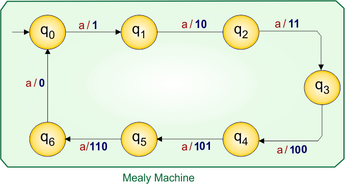
Let’s explain the Moore to Mealy conversion process
At state “q0”:
- For input “a”, the Moore machine moves to state “q1”, and since “q1” gives output “1”, the corresponding Mealy machine transition (over arrow) is written as a/1.
At state “q1”:
- For input “a”, the Moore machine moves to state “q2”, and since “q2” gives output “10”, the corresponding Mealy machine transition (over arrow) is written as a/10.
At state “q2”:
- For input “a”, the Moore machine moves to state “q3”, and since “q3” gives output “11”, the corresponding Mealy machine transition (over arrow) is written as a/11.
At state “q3”:
- For input “a”, the Moore machine moves to state “q4”, and since “q4” gives output “110”, the corresponding Mealy machine transition (over arrow) is written as a/110.
At state “q4”:
- For input “a”, the Moore machine moves to state “q5”, and since “q5” gives output “101”, the corresponding Mealy machine transition (over arrow) is written as a/101.
At state “q5”:
- For input “a”, the Moore machine moves to state “q6”, and since “q6” gives output “110”, the corresponding Mealy machine transition (over arrow) is written as a/110.
At state “q6”:
- For input “a”, the Moore machine moves to state “q0”, and since “q0” gives output “0”, the corresponding Mealy machine transition (over arrow) is written as a/0.
Mealy Machine Transition Table
The transition table of the above Mealy machine is given below
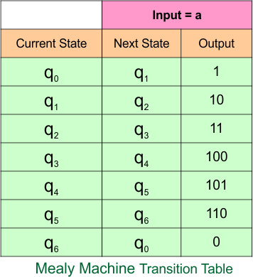
The explanation of the above Mealy Machine transition table is given below
- In the current state “q0”, when the input is “a”, the next state remains “q1” and the output is “1”.
- In the current state “q1”, when the input is “a”, the next state remains “q2” and the output is “10”.
- In the current state “q2”, when the input is “a”, the next state remains “q3” and the output is “11”.
- In the current state “q3”, when the input is “a”, the next state remains “q4” and the output is “100”.
- In the current state “q4”, when the input is “a”, the next state remains “q5” and the output is “101”.
- In the current state “q5”, when the input is “a”, the next state remains “q6” and the output is “110”.
- In the current state “q6”, when the input is “a”, the next state remains “q0” and the output is “0”.
Example 7.2: 7-States, 2-Input Symbol
Moore Machine
Here is the Moore Machine, which contains a seven-state (“q0”, “q1”, “q2”, “q3”, “q4”, “q5” and “q6”) with outputs (“0”, “1”, “10”, “11”, “100”, “101” and “110”) and two input symbols (“a”, “b”). We will convert it into a corresponding Mealy machine.
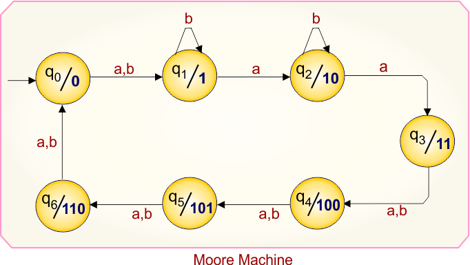
Moore Machine Transition Table
Here is the transition table for the given Moore machine
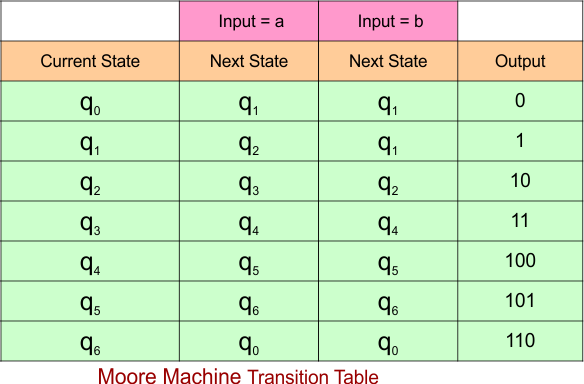
The explanation of the above Mealy Machine transition table is given below
At the current state “q0”,
- When the input is “a”, the next state remains “q1” and the output is “0”.
- When the input is “b”, the next state remains “q1” and the output is “0”.
At the current state “q1”,
- when the input is “a”, the next state remains “q2” and the output is “1”.
- When the input is “b”, the next state remains “q1” and the output is “1”.
At the current state “q2”,
- when the input is “a”, the next state remains “q3” and the output is “10”.
- When the input is “b”, the next state remains “q2” and the output is “10”.
At the current state “q3”,
- when the input is “a”, the next state remains “q4” and the output is “11”.
- When the input is “b”, the next state remains “q4” and the output is “11”.
At the current state “q4”,
- when the input is “a”, the next state remains “q5” and the output is “100”.
- When the input is “b”, the next state remains “q5” and the output is “100”.
At the current state “q5”,
- when the input is “a”, the next state remains “q6” and the output is “101”.
- When the input is “b”, the next state remains “q6” and the output is “101”.
At the current state “q6”,
- when the input is “a”, the next state remains “q0” and the output is “110”.
- When the input is “b”, the next state remains “q0” and the output is “110”.
Mealy Machine
According to the rule of Moore to Mealy conversion, the corresponding Mealy machine is given below,
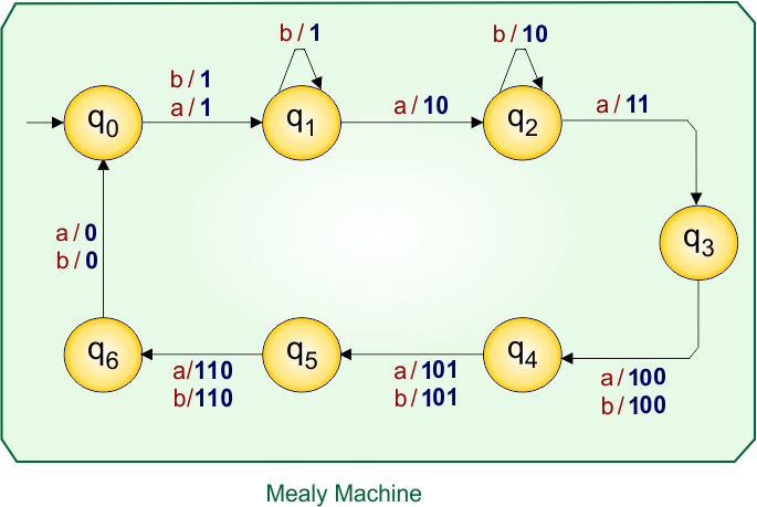
Let’s explain the Moore to Mealy conversion process
At state “q0”:
- For input “a”, the Moore machine moves to state “q1”, and since “q1” gives output “1”, the corresponding Mealy machine transition (over arrow) is written as a/1.
- For input “b”, the Moore machine moves to state “q1”, and since “q1” gives output “1”, the corresponding Mealy machine transition (over arrow) is written as b/1.
At state “q1”:
- For input “a”, the Moore machine moves to state “q2”, and since “q2” gives output “10”, the corresponding Mealy machine transition (over arrow) is written as a/10.
- For input “b”, the Moore machine moves to state “q1”, and since “q1” gives output “1”, the corresponding Mealy machine transition (over arrow) is written as b/1.
At state “q2”:
- For input “a”, the Moore machine moves to state “q3”, and since “q3” gives output “11”, the corresponding Mealy machine transition (over arrow) is written as a/11.
- For input “b”, the Moore machine moves to state “q2”, and since “q2” gives output “10”, the corresponding Mealy machine transition (over arrow) is written as b/10.
At state “q3”:
- For input “a”, the Moore machine moves to state “q4”, and since “q4” gives output “100”, the corresponding Mealy machine transition (over arrow) is written as a/100.
- For input “b”, the Moore machine moves to state “q4”, and since “q4” gives output “100”, the corresponding Mealy machine transition (over arrow) is written as b/100.
At state “q4”:
- For input “a”, the Moore machine moves to state “q5”, and since “q5” gives output “101”, the corresponding Mealy machine transition (over arrow) is written as a/101.
- For input “b”, the Moore machine moves to state “q5”, and since “q5” gives output “101”, the corresponding Mealy machine transition (over arrow) is written as b/101.
At state “q5”:
- For input “a”, the Moore machine moves to state “q6”, and since “q6” gives output “110”, the corresponding Mealy machine transition (over arrow) is written as a/110.
- For input “b”, the Moore machine moves to state “q6”, and since “q6” gives output “110”, the corresponding Mealy machine transition (over arrow) is written as b/110.
At state “q6”:
- For input “a”, the Moore machine moves to state “q0”, and since “q0” gives output “0”, the corresponding Mealy machine transition (over arrow) is written as a/0.
- For input “b”, the Moore machine moves to state “q0”, and since “q0” gives output “0”, the corresponding Mealy machine transition (over arrow) is written as b/0.
Mealy Machine Transition Table
The transition table of the above Mealy machine is given below
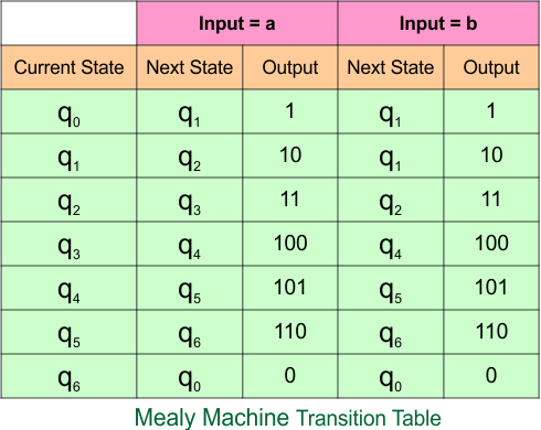
The explanation of the above Mealy Machine transition table is given below
In the current state “q0”,
- when the input is “a”, the next state remains “q1” and the output is “1”.
- When the input is “b”, the next state remains “q1” and the output is “1”.
In the current state “q1”,
- when the input is “a”, the next state remains “q2” and the output is “10”.
- When the input is “b”, the next state remains “q1” and the output is “1”.
In the current state “q2”,
- when the input is “a”, the next state remains “q3” and the output is “11”.
- When the input is “b”, the next state remains “q2” and the output is “10”.
In the current state “q3”,
- when the input is “a”, the next state remains “q4” and the output is “100”.
- When the input is “b”, the next state remains “q4” and the output is “100”.
In the current state “q4”,
- when the input is “a”, the next state remains “q5” and the output is “101”.
- When the input is “b”, the next state remains “q5” and the output is “101”.
In the current state “q5”,
- when the input is “a”, the next state remains “q6” and the output is “110”.
- When the input is “b”, the next state remains “q6” and the output is “110”.
In the current state “q6”,
- when the input is “a”, the next state remains “q0” and the output is “0”.
- When the input is “b”, the next state remains “q0” and the output is “0”.
Example 7.3: 7-States, 3-Input Symbol
Moore Machine
Here is the Moore Machine, which contains a seven-state (“q0”, “q1”, “q2”, “q3”, “q4”, “q5” and “q6”) with outputs (“0”, “1”, “10”, “11”, “100”, “101” and “110”) and three input symbols (“a”, “b”, “c”). We will convert it into a corresponding Mealy machine.
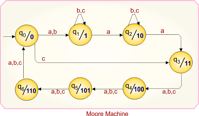
Moore Machine Transition Table
Here is the transition table for the given Moore machine
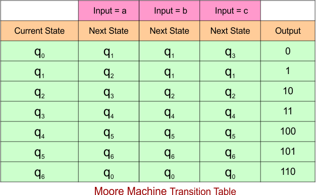
The explanation of the above Mealy Machine transition table is given below
At the current state “q0”,
- When the input is “a”, the next state remains “q1” and the output is “0”.
- When the input is “b”, the next state remains “q1” and the output is “0”.
- When the input is “c”, the next state remains “q3” and the output is “0”.
At the current state “q1”,
- when the input is “a”, the next state remains “q2” and the output is “1”.
- When the input is “b”, the next state remains “q1” and the output is “1”.
- When the input is “c”, the next state remains “q1” and the output is “1”.
At the current state “q2”,
- when the input is “a”, the next state remains “q3” and the output is “10”.
- When the input is “b”, the next state remains “q2” and the output is “10”.
- When the input is “c”, the next state remains “q2” and the output is “10”.
At the current state “q3”,
- when the input is “a”, the next state remains “q4” and the output is “11”.
- When the input is “b”, the next state remains “q4” and the output is “11”.
- When the input is “c”, the next state remains “q4” and the output is “11”.
At the current state “q4”,
- when the input is “a”, the next state remains “q5” and the output is “100”.
- When the input is “b”, the next state remains “q5” and the output is “100”.
- When the input is “c”, the next state remains “q5” and the output is “100”.
At the current state “q5”,
- when the input is “a”, the next state remains “q6” and the output is “101”.
- When the input is “b”, the next state remains “q6” and the output is “101”.
- When the input is “c”, the next state remains “q6” and the output is “101”.
At the current state “q6”,
- when the input is “a”, the next state remains “q0” and the output is “110”.
- When the input is “b”, the next state remains “q0” and the output is “110”.
- When the input is “c”, the next state remains “q0” and the output is “110”.
Mealy Machine
According to the rule of Moore to Mealy conversion, the corresponding Mealy machine is given below,
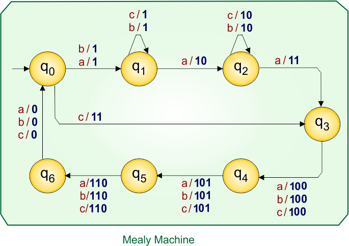
Let’s explain the Moore to Mealy conversion process
At state “q0”:
- For input “a”, the Moore machine moves to state “q1”, and since “q1” gives output “1”, the corresponding Mealy machine transition (over arrow) is written as a/1.
- For input “b”, the Moore machine moves to state “q1”, and since “q1” gives output “1”, the corresponding Mealy machine transition (over arrow) is written as b/1.
- For input “c”, the Moore machine moves to state “q3”, and since “q3” gives output “11”, the corresponding Mealy machine transition (over arrow) is written as c/11.
At state “q1”:
- For input “a”, the Moore machine moves to state “q2”, and since “q2” gives output “10”, the corresponding Mealy machine transition (over arrow) is written as a/10.
- For input “b”, the Moore machine moves to state “q1”, and since “q1” gives output “1”, the corresponding Mealy machine transition (over arrow) is written as b/1.
- For input “c”, the Moore machine moves to state “q1”, and since “q1” gives output “1”, the corresponding Mealy machine transition (over arrow) is written as c/1.
At state “q2”:
- For input “a”, the Moore machine moves to state “q3”, and since “q3” gives output “11”, the corresponding Mealy machine transition (over arrow) is written as a/11.
- For input “b”, the Moore machine moves to state “q2”, and since “q2” gives output “10”, the corresponding Mealy machine transition (over arrow) is written as b/10.
- For input “c”, the Moore machine moves to state “q2”, and since “q2” gives output “10”, the corresponding Mealy machine transition (over arrow) is written as c/10.
At state “q3”:
- For input “a”, the Moore machine moves to state “q4”, and since “q4” gives output “100”, the corresponding Mealy machine transition (over arrow) is written as a/100.
- For input “b”, the Moore machine moves to state “q4”, and since “q4” gives output “100”, the corresponding Mealy machine transition (over arrow) is written as b/100.
- For input “c”, the Moore machine moves to state “q4”, and since “q4” gives output “100”, the corresponding Mealy machine transition (over arrow) is written as c/100.
At state “q4”:
- For input “a”, the Moore machine moves to state “q5”, and since “q5” gives output “101”, the corresponding Mealy machine transition (over arrow) is written as a/101.
- For input “b”, the Moore machine moves to state “q5”, and since “q5” gives output “101”, the corresponding Mealy machine transition (over arrow) is written as b/101.
- For input “c”, the Moore machine moves to state “q5”, and since “q5” gives output “101”, the corresponding Mealy machine transition (over arrow) is written as c/101.
At state “q5”:
- For input “a”, the Moore machine moves to state “q6”, and since “q6” gives output “110”, the corresponding Mealy machine transition (over arrow) is written as a/110.
- For input “b”, the Moore machine moves to state “q6”, and since “q6” gives output “110”, the corresponding Mealy machine transition (over arrow) is written as b/110.
- For input “c”, the Moore machine moves to state “q6”, and since “q6” gives output “110”, the corresponding Mealy machine transition (over arrow) is written as c/110.
At state “q6”:
- For input “a”, the Moore machine moves to state “q0”, and since “q0” gives output “0”, the corresponding Mealy machine transition (over arrow) is written as a/0.
- For input “b”, the Moore machine moves to state “q0”, and since “q0” gives output “0”, the corresponding Mealy machine transition (over arrow) is written as b/0.
- For input “c”, the Moore machine moves to state “q0”, and since “q0” gives output “0”, the corresponding Mealy machine transition (over arrow) is written as c/0.
Mealy Machine Transition Table
The transition table of the above Mealy machine is given below
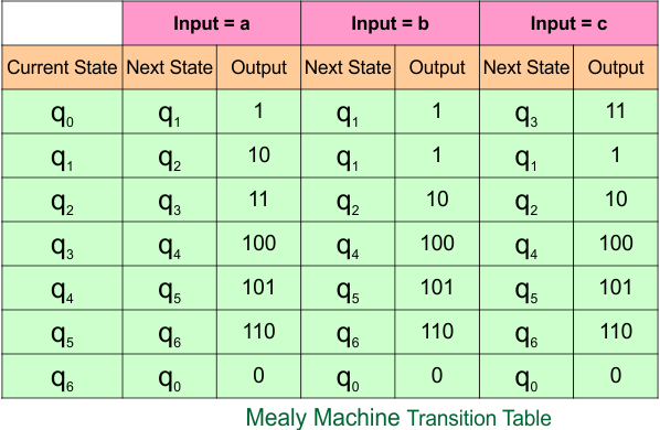
The explanation of the above Mealy Machine transition table is given below
In the current state “q0”,
- when the input is “a”, the next state remains “q1” and the output is “1”.
- When the input is “b”, the next state remains “q1” and the output is “1”.
- When the input is “c”, the next state remains “q3” and the output is “11”.
In the current state “q1”,
- when the input is “a”, the next state remains “q2” and the output is “10”.
- When the input is “b”, the next state remains “q1” and the output is “1”.
- When the input is “c”, the next state remains “q1” and the output is “1”.
In the current state “q2”,
- when the input is “a”, the next state remains “q3” and the output is “11”.
- When the input is “b”, the next state remains “q2” and the output is “10”.
- When the input is “c”, the next state remains “q2” and the output is “10”.
In the current state “q3”,
- when the input is “a”, the next state remains “q4” and the output is “100”.
- When the input is “b”, the next state remains “q4” and the output is “100”.
- When the input is “c”, the next state remains “q4” and the output is “100”.
In the current state “q4”,
- when the input is “a”, the next state remains “q5” and the output is “101”.
- When the input is “b”, the next state remains “q5” and the output is “101”.
- When the input is “c”, the next state remains “q5” and the output is “101”.
In the current state “q5”,
- when the input is “a”, the next state remains “q6” and the output is “110”.
- When the input is “b”, the next state remains “q6” and the output is “110”.
- When the input is “c”, the next state remains “q6” and the output is “110”.
In the current state “q6”,
- when the input is “a”, the next state remains “q0” and the output is “0”.
- When the input is “b”, the next state remains “q0” and the output is “0”.
- When the input is “c”, the next state remains “q0” and the output is “0”.
Example 7.4: 7-States, 4-Input Symbol
Moore Machine
Here is the Moore Machine, which contains a seven-state (“q0”, “q1”, “q2”, “q3”, “q4”, “q5” and “q6”) with outputs (“0”, “1”, “10”, “11”, “100”, “101” and “110”) and four input symbols (“a”, “b”, “c”, and “d”). We will convert it into a corresponding Mealy machine.
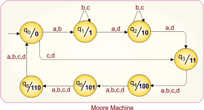
Moore Machine Transition Table
Here is the transition table for the given Moore machine
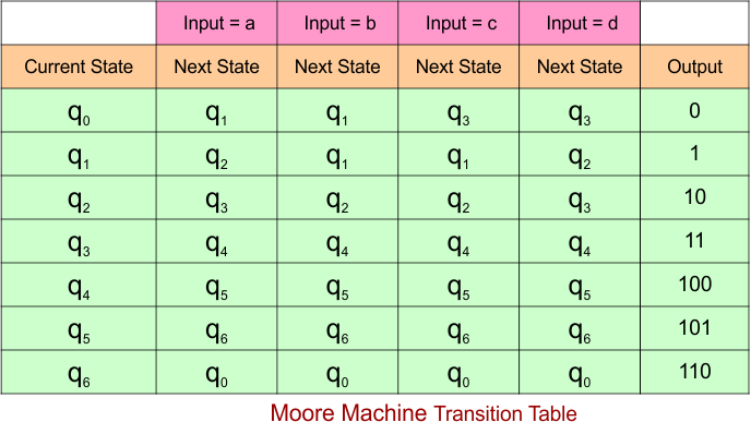
The explanation of the above Mealy Machine transition table is given below
At the current state “q0”,
- When the input is “a”, the next state remains “q1” and the output is “0”.
- When the input is “b”, the next state remains “q1” and the output is “0”.
- When the input is “c”, the next state remains “q3” and the output is “0”.
- When the input is “d”, the next state remains “q3” and the output is “0”.
At the current state “q1”,
- when the input is “a”, the next state remains “q2” and the output is “1”.
- When the input is “b”, the next state remains “q1” and the output is “1”.
- When the input is “c”, the next state remains “q1” and the output is “1”.
- when the input is “d”, the next state remains “q2” and the output is “1”.
At the current state “q2”,
- when the input is “a”, the next state remains “q3” and the output is “10”.
- When the input is “b”, the next state remains “q2” and the output is “10”.
- When the input is “c”, the next state remains “q2” and the output is “10”.
- when the input is “d”, the next state remains “q3” and the output is “10”.
At the current state “q3”,
- when the input is “a”, the next state remains “q4” and the output is “11”.
- When the input is “b”, the next state remains “q4” and the output is “11”.
- When the input is “c”, the next state remains “q4” and the output is “11”.
- When the input is “d”, the next state remains “q4” and the output is “11”.
At the current state “q4”,
- when the input is “a”, the next state remains “q5” and the output is “100”.
- When the input is “b”, the next state remains “q5” and the output is “100”.
- When the input is “c”, the next state remains “q5” and the output is “100”.
- When the input is “d”, the next state remains “q5” and the output is “100”.
At the current state “q5”,
- when the input is “a”, the next state remains “q6” and the output is “101”.
- When the input is “b”, the next state remains “q6” and the output is “101”.
- When the input is “c”, the next state remains “q6” and the output is “101”.
- When the input is “d”, the next state remains “q6” and the output is “101”.
At the current state “q6”,
- when the input is “a”, the next state remains “q0” and the output is “110”.
- When the input is “b”, the next state remains “q0” and the output is “110”.
- When the input is “c”, the next state remains “q0” and the output is “110”.
- When the input is “d”, the next state remains “q0” and the output is “110”.
Mealy Machine
According to the rule of Moore to Mealy conversion, the corresponding Mealy machine is given below,
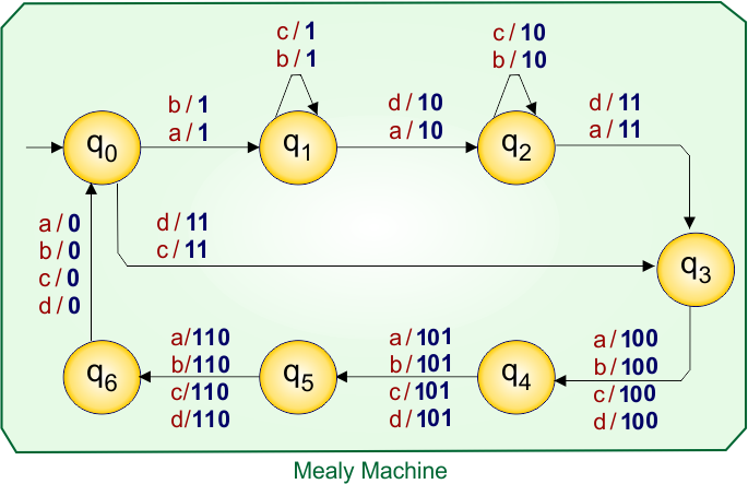
Let’s explain the Moore to Mealy conversion process
At state “q0”:
- For input “a”, the Moore machine moves to state “q1”, and since “q1” gives output “1”, the corresponding Mealy machine transition (over arrow) is written as a/1.
- For input “b”, the Moore machine moves to state “q1”, and since “q1” gives output “1”, the corresponding Mealy machine transition (over arrow) is written as b/1.
- For input “c”, the Moore machine moves to state “q3”, and since “q3” gives output “11”, the corresponding Mealy machine transition (over arrow) is written as c/11.
- For input “d”, the Moore machine moves to state “q3”, and since “q3” gives output “11”, the corresponding Mealy machine transition (over arrow) is written as d/11.
At state “q1”:
- For input “a”, the Moore machine moves to state “q2”, and since “q2” gives output “10”, the corresponding Mealy machine transition (over arrow) is written as a/10.
- For input “b”, the Moore machine moves to state “q1”, and since “q1” gives output “1”, the corresponding Mealy machine transition (over arrow) is written as b/1.
- For input “c”, the Moore machine moves to state “q1”, and since “q1” gives output “1”, the corresponding Mealy machine transition (over arrow) is written as c/1.
- For input “d”, the Moore machine moves to state “q2”, and since “q2” gives output “10”, the corresponding Mealy machine transition (over arrow) is written as d/10.
At state “q2”:
- For input “a”, the Moore machine moves to state “q3”, and since “q3” gives output “11”, the corresponding Mealy machine transition (over arrow) is written as a/11.
- For input “b”, the Moore machine moves to state “q2”, and since “q2” gives output “10”, the corresponding Mealy machine transition (over arrow) is written as b/10.
- For input “c”, the Moore machine moves to state “q2”, and since “q2” gives output “10”, the corresponding Mealy machine transition (over arrow) is written as c/10.
- For input “d”, the Moore machine moves to state “q3”, and since “q3” gives output “11”, the corresponding Mealy machine transition (over arrow) is written as d/11.
At state “q3”:
- For input “a”, the Moore machine moves to state “q4”, and since “q4” gives output “100”, the corresponding Mealy machine transition (over arrow) is written as a/100.
- For input “b”, the Moore machine moves to state “q4”, and since “q4” gives output “100”, the corresponding Mealy machine transition (over arrow) is written as b/100.
- For input “c”, the Moore machine moves to state “q4”, and since “q4” gives output “100”, the corresponding Mealy machine transition (over arrow) is written as c/100.
- For input “d”, the Moore machine moves to state “q4”, and since “q4” gives output “100”, the corresponding Mealy machine transition (over arrow) is written as d/100.
At state “q4”:
- For input “a”, the Moore machine moves to state “q5”, and since “q5” gives output “101”, the corresponding Mealy machine transition (over arrow) is written as a/101.
- For input “b”, the Moore machine moves to state “q5”, and since “q5” gives output “101”, the corresponding Mealy machine transition (over arrow) is written as b/101.
- For input “c”, the Moore machine moves to state “q5”, and since “q5” gives output “101”, the corresponding Mealy machine transition (over arrow) is written as c/101.
- For input “d”, the Moore machine moves to state “q5”, and since “q5” gives output “101”, the corresponding Mealy machine transition (over arrow) is written as d/101.
At state “q5”:
- For input “a”, the Moore machine moves to state “q6”, and since “q6” gives output “110”, the corresponding Mealy machine transition (over arrow) is written as a/110.
- For input “b”, the Moore machine moves to state “q6”, and since “q6” gives output “110”, the corresponding Mealy machine transition (over arrow) is written as b/110.
- For input “c”, the Moore machine moves to state “q6”, and since “q6” gives output “110”, the corresponding Mealy machine transition (over arrow) is written as c/110.
- For input “d”, the Moore machine moves to state “q6”, and since “q6” gives output “110”, the corresponding Mealy machine transition (over arrow) is written as d/110.
At state “q6”:
- For input “a”, the Moore machine moves to state “q0”, and since “q0” gives output “0”, the corresponding Mealy machine transition (over arrow) is written as a/0.
- For input “b”, the Moore machine moves to state “q0”, and since “q0” gives output “0”, the corresponding Mealy machine transition (over arrow) is written as b/0.
- For input “c”, the Moore machine moves to state “q0”, and since “q0” gives output “0”, the corresponding Mealy machine transition (over arrow) is written as c/0.
- For input “d”, the Moore machine moves to state “q0”, and since “q0” gives output “0”, the corresponding Mealy machine transition (over arrow) is written as d/0.
Mealy Machine Transition Table
The transition table of the above Mealy machine is given below
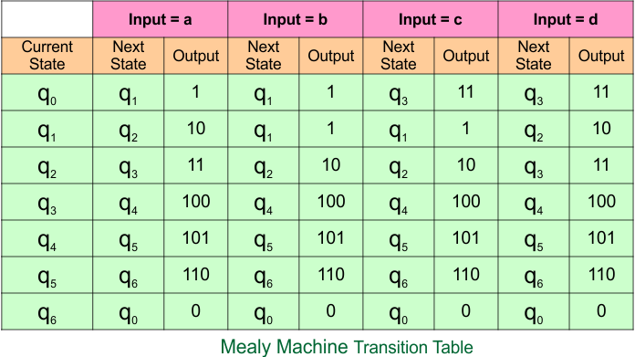
The explanation of the above Mealy Machine transition table is given below
In the current state “q0”,
- when the input is “a”, the next state remains “q1” and the output is “1”.
- When the input is “b”, the next state remains “q1” and the output is “1”.
- When the input is “c”, the next state remains “q3” and the output is “11”.
- When the input is “d”, the next state remains “q3” and the output is “11”.
In the current state “q1”,
- when the input is “a”, the next state remains “q2” and the output is “10”.
- When the input is “b”, the next state remains “q1” and the output is “1”.
- When the input is “c”, the next state remains “q1” and the output is “1”.
- When the input is “d”, the next state remains “q2” and the output is “10”.
In the current state “q2”,
- when the input is “a”, the next state remains “q3” and the output is “11”.
- When the input is “b”, the next state remains “q2” and the output is “10”.
- When the input is “c”, the next state remains “q2” and the output is “10”.
In the current state “q3”,
- when the input is “a”, the next state remains “q4” and the output is “100”.
- When the input is “b”, the next state remains “q4” and the output is “100”.
- When the input is “c”, the next state remains “q4” and the output is “100”.
- When the input is “d”, the next state remains “q3” and the output is “11”.
In the current state “q4”,
- when the input is “a”, the next state remains “q5” and the output is “101”.
- When the input is “b”, the next state remains “q5” and the output is “101”.
- When the input is “c”, the next state remains “q5” and the output is “101”.
- When the input is “d”, the next state remains “q5” and the output is “101”.
In the current state “q5”,
- when the input is “a”, the next state remains “q6” and the output is “110”.
- When the input is “b”, the next state remains “q6” and the output is “110”.
- When the input is “c”, the next state remains “q6” and the output is “110”.
- When the input is “d”, the next state remains “q6” and the output is “110”.
In the current state “q6”,
- when the input is “a”, the next state remains “q0” and the output is “0”.
- When the input is “b”, the next state remains “q0” and the output is “0”.
- When the input is “c”, the next state remains “q0” and the output is “0”.
- When the input is “d”, the next state remains “q0” and the output is “0”.
Category 8: Moore to Mealy Conversion Using 8-States
Example 8.1: 8-States, 1-Input Symbol
Moore Machine
Here is the Moore Machine, which contains a seven-state (“q0”, “q1”, “q2”, “q3”, “q4”, “q5”, “q6” and “q7”) with outputs (“0”, “1”, “10”, “11”, “100”, “101”, “110”, and “111”) and one input symbol (“a”). We will convert it into a corresponding Mealy machine.
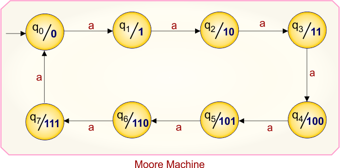
Moore Machine Transition Table
Here is the transition table for the given Moore machine
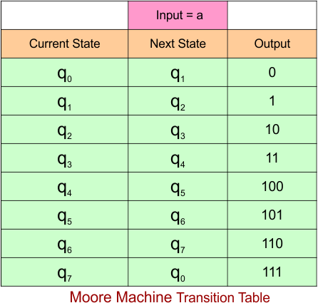
The explanation of the above Mealy Machine transition table is given below
- At the current state “q0”, when the input is “a”, the next state remains “q1” and the output is “0”.
- At the current state “q1”, when the input is “a”, the next state remains “q2” and the output is “1”.
- At the current state “q2”, when the input is “a”, the next state remains “q3” and the output is “10”.
- At the current state “q3”, when the input is “a”, the next state remains “q4” and the output is “11”.
- At the current state “q4”, when the input is “a”, the next state remains “q5” and the output is “100”.
- At the current state “q5”, when the input is “a”, the next state remains “q6” and the output is “101”.
- At the current state “q6”, when the input is “a”, the next state remains “q7” and the output is “110”.
- At the current state “q7”, when the input is “a”, the next state remains “q0” and the output is “111”.
Mealy Machine
According to the rule of Moore to Mealy conversion, the corresponding Mealy machine is given below,
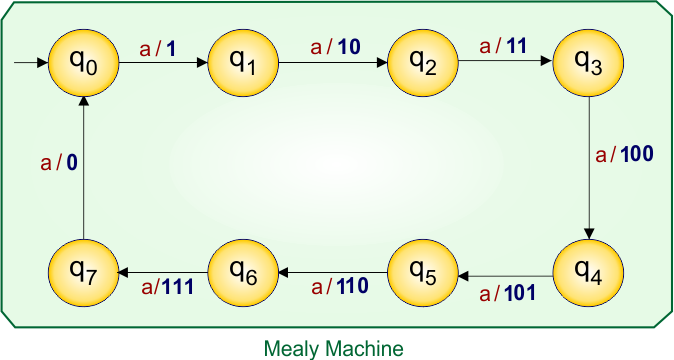
Let’s explain the Moore to Mealy conversion process
At state “q0”:
- For input “a”, the Moore machine moves to state “q1”, and since “q1” gives output “1”, the corresponding Mealy machine transition (over arrow) is written as a/1.
At state “q1”:
- For input “a”, the Moore machine moves to state “q2”, and since “q2” gives output “10”, the corresponding Mealy machine transition (over arrow) is written as a/10.
At state “q2”:
- For input “a”, the Moore machine moves to state “q3”, and since “q3” gives output “11”, the corresponding Mealy machine transition (over arrow) is written as a/11.
At state “q3”:
- For input “a”, the Moore machine moves to state “q4”, and since “q4” gives output “110”, the corresponding Mealy machine transition (over arrow) is written as a/110.
At state “q4”:
- For input “a”, the Moore machine moves to state “q5”, and since “q5” gives output “101”, the corresponding Mealy machine transition (over arrow) is written as a/101.
At state “q5”:
- For input “a”, the Moore machine moves to state “q6”, and since “q6” gives output “110”, the corresponding Mealy machine transition (over arrow) is written as a/110.
At state “q6”:
- For input “a”, the Moore machine moves to state “q7”, and since “q7” gives output “111”, the corresponding Mealy machine transition (over arrow) is written as a/111.
At state “q7”:
- For input “a”, the Moore machine moves to state “q0”, and since “q0” gives output “0”, the corresponding Mealy machine transition (over arrow) is written as a/0.
Mealy Machine Transition Table
The transition table of the above Mealy machine is given below
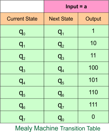
The explanation of the above Mealy Machine transition table is given below
- In the current state “q0”, when the input is “a”, the next state remains “q1” and the output is “1”.
- In the current state “q1”, when the input is “a”, the next state remains “q2” and the output is “10”.
- In the current state “q2”, when the input is “a”, the next state remains “q3” and the output is “11”.
- In the current state “q3”, when the input is “a”, the next state remains “q4” and the output is “100”.
- In the current state “q4”, when the input is “a”, the next state remains “q5” and the output is “101”.
- In the current state “q5”, when the input is “a”, the next state remains “q6” and the output is “110”.
- In the current state “q6”, when the input is “a”, the next state remains “q7” and the output is “111”.
- In the current state “q7”, when the input is “a”, the next state remains “q0” and the output is “0”.
Example 8.2: 8-States, 2-Input Symbol
Moore Machine
Here is the Moore Machine, which contains a seven-state (“q0”, “q1”, “q2”, “q3”, “q4”, “q5”, “q6” and “q7”) with outputs (“0”, “1”, “10”, “11”, “100”, “101”, “110”, and “111”) and two input symbols (“a”, “b”). We will convert it into a corresponding Mealy machine.
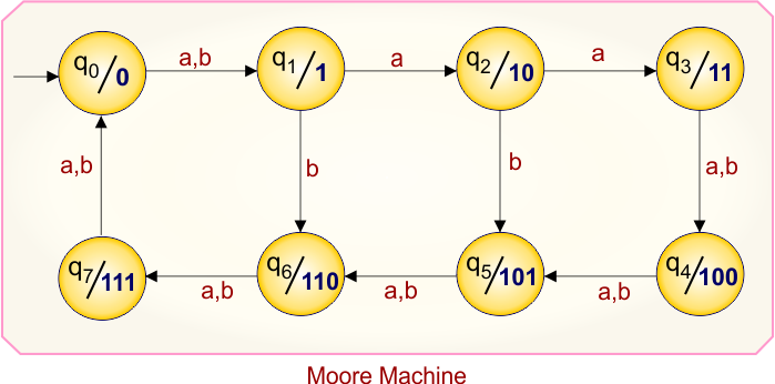
Moore Machine Transition Table
Here is the transition table for the given Moore machine
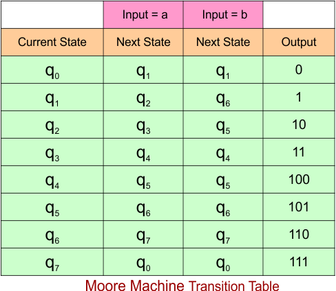
The explanation of the above Mealy Machine transition table is given below
At the current state “q0”,
- When the input is “a”, the next state remains “q1” and the output is “0”.
- When the input is “b”, the next state remains “q1” and the output is “0”.
At the current state “q1”,
- when the input is “a”, the next state remains “q2” and the output is “1”.
- When the input is “b”, the next state remains “q6” and the output is “1”.
At the current state “q2”,
- when the input is “a”, the next state remains “q3” and the output is “10”.
- When the input is “b”, the next state remains “q5” and the output is “10”.
At the current state “q3”,
- when the input is “a”, the next state remains “q4” and the output is “11”.
- When the input is “b”, the next state remains “q4” and the output is “11”.
At the current state “q4”,
- when the input is “a”, the next state remains “q5” and the output is “100”.
- When the input is “b”, the next state remains “q5” and the output is “100”.
At the current state “q5”,
- when the input is “a”, the next state remains “q6” and the output is “101”.
- When the input is “b”, the next state remains “q6” and the output is “101”.
At the current state “q6”,
- when the input is “a”, the next state remains “q7” and the output is “110”.
- When the input is “b”, the next state remains “q7” and the output is “110”.
At the current state “q7”,
- when the input is “a”, the next state remains “q0” and the output is “111”.
- When the input is “b”, the next state remains “q0” and the output is “111”.
Mealy Machine
According to the rule of Moore to Mealy conversion, the corresponding Mealy machine is given below,
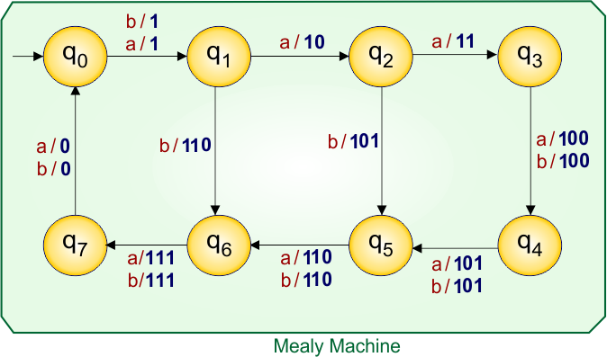
Let’s explain the Moore to Mealy conversion process
At state “q0”:
- For input “a”, the Moore machine moves to state “q1”, and since “q1” gives output “1”, the corresponding Mealy machine transition (over arrow) is written as a/1.
- For input “b”, the Moore machine moves to state “q1”, and since “q1” gives output “1”, the corresponding Mealy machine transition (over arrow) is written as b/1.
At state “q1”:
- For input “a”, the Moore machine moves to state “q2”, and since “q2” gives output “10”, the corresponding Mealy machine transition (over arrow) is written as a/10.
- For input “b”, the Moore machine moves to state “q6”, and since “q6” gives output “110”, the corresponding Mealy machine transition (over arrow) is written as b/110.
At state “q2”:
- For input “a”, the Moore machine moves to state “q3”, and since “q3” gives output “11”, the corresponding Mealy machine transition (over arrow) is written as a/11.
- For input “b”, the Moore machine moves to state “q5”, and since “q5” gives output “101”, the corresponding Mealy machine transition (over arrow) is written as b/101.
At state “q3”:
- For input “a”, the Moore machine moves to state “q4”, and since “q4” gives output “100”, the corresponding Mealy machine transition (over arrow) is written as a/100.
- For input “b”, the Moore machine moves to state “q4”, and since “q4” gives output “100”, the corresponding Mealy machine transition (over arrow) is written as b/100.
At state “q4”:
- For input “a”, the Moore machine moves to state “q5”, and since “q5” gives output “101”, the corresponding Mealy machine transition (over arrow) is written as a/101.
- For input “b”, the Moore machine moves to state “q5”, and since “q5” gives output “101”, the corresponding Mealy machine transition (over arrow) is written as b/101.
At state “q5”:
- For input “a”, the Moore machine moves to state “q6”, and since “q6” gives output “110”, the corresponding Mealy machine transition (over arrow) is written as a/110.
- For input “b”, the Moore machine moves to state “q6”, and since “q6” gives output “110”, the corresponding Mealy machine transition (over arrow) is written as b/110.
At state “q6”:
- For input “a”, the Moore machine moves to state “q7”, and since “q7” gives output “111”, the corresponding Mealy machine transition (over arrow) is written as a/111.
- For input “b”, the Moore machine moves to state “q7”, and since “q7” gives output “111”, the corresponding Mealy machine transition (over arrow) is written as b/111.
At state “q7”:
- For input “a”, the Moore machine moves to state “q0”, and since “q0” gives output “0”, the corresponding Mealy machine transition (over arrow) is written as a/0.
- For input “b”, the Moore machine moves to state “q0”, and since “q0” gives output “0”, the corresponding Mealy machine transition (over arrow) is written as b/0.
Mealy Machine Transition Table
The transition table of the above Mealy machine is given below
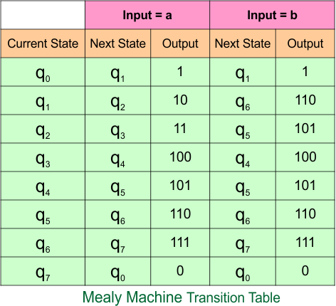
The explanation of the above Mealy Machine transition table is given below
In the current state “q0”,
- when the input is “a”, the next state remains “q1” and the output is “1”.
- When the input is “b”, the next state remains “q1” and the output is “1”.
In the current state “q1”,
- when the input is “a”, the next state remains “q2” and the output is “10”.
- When the input is “b”, the next state remains “q6” and the output is “110”.
In the current state “q2”,
- when the input is “a”, the next state remains “q3” and the output is “11”.
- When the input is “b”, the next state remains “q5” and the output is “101”.
In the current state “q3”,
- when the input is “a”, the next state remains “q4” and the output is “100”.
- When the input is “b”, the next state remains “q4” and the output is “100”.
In the current state “q4”,
- when the input is “a”, the next state remains “q5” and the output is “101”.
- When the input is “b”, the next state remains “q5” and the output is “101”.
In the current state “q5”,
- when the input is “a”, the next state remains “q6” and the output is “110”.
- When the input is “b”, the next state remains “q6” and the output is “110”.
In the current state “q6”,
- when the input is “a”, the next state remains “q7” and the output is “111”.
- When the input is “b”, the next state remains “q7” and the output is “111”.
In the current state “q7”,
- when the input is “a”, the next state remains “q0” and the output is “0”.
- When the input is “b”, the next state remains “q0” and the output is “0”.
Example 8.3: 8-States, 3-Input Symbol
Moore Machine
Here is the Moore Machine, which contains a seven-state (“q0”, “q1”, “q2”, “q3”, “q4”, “q5”, “q6” and “q7”) with outputs (“0”, “1”, “10”, “11”, “100”, “101”, “110”, and “111”) and two input symbols (“a”, “b”, “c”). We will convert it into a corresponding Mealy machine.
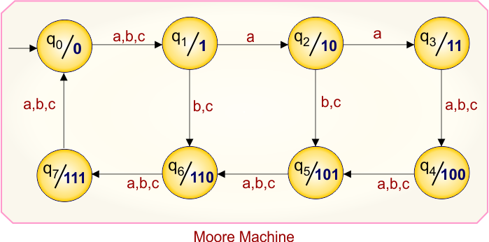
Moore Machine Transition Table
Here is the transition table for the given Moore machine
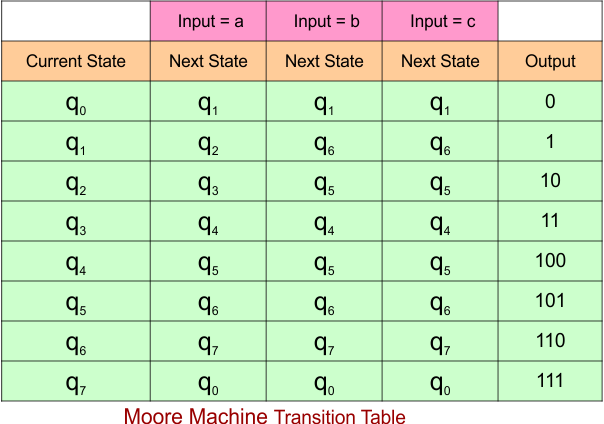
The explanation of the above Mealy Machine transition table is given below
At the current state “q0”,
- When the input is “a”, the next state remains “q1” and the output is “0”.
- When the input is “b”, the next state remains “q1” and the output is “0”.
- When the input is “c”, the next state remains “q1” and the output is “0”.
At the current state “q1”,
- when the input is “a”, the next state remains “q2” and the output is “1”.
- When the input is “b”, the next state remains “q6” and the output is “1”.
- When the input is “c”, the next state remains “q6” and the output is “1”.
At the current state “q2”,
- when the input is “a”, the next state remains “q3” and the output is “10”.
- When the input is “b”, the next state remains “q5” and the output is “10”.
- When the input is “c”, the next state remains “q5” and the output is “10”.
At the current state “q3”,
- when the input is “a”, the next state remains “q4” and the output is “11”.
- When the input is “b”, the next state remains “q4” and the output is “11”.
- When the input is “c”, the next state remains “q4” and the output is “11”.
At the current state “q4”,
- when the input is “a”, the next state remains “q5” and the output is “100”.
- When the input is “b”, the next state remains “q5” and the output is “100”.
- When the input is “c”, the next state remains “q5” and the output is “100”.
At the current state “q5”,
- when the input is “a”, the next state remains “q6” and the output is “101”.
- When the input is “b”, the next state remains “q6” and the output is “101”.
- When the input is “c”, the next state remains “q6” and the output is “101”.
At the current state “q6”,
- when the input is “a”, the next state remains “q7” and the output is “110”.
- When the input is “b”, the next state remains “q7” and the output is “110”.
- When the input is “c”, the next state remains “q7” and the output is “110”.
At the current state “q7”,
- when the input is “a”, the next state remains “q0” and the output is “111”.
- When the input is “b”, the next state remains “q0” and the output is “111”.
- When the input is “c”, the next state remains “q0” and the output is “111”.
Mealy Machine
According to the rule of Moore to Mealy conversion, the corresponding Mealy machine is given below,
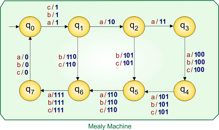
Let’s explain the Moore to Mealy conversion process
At state “q0”:
- For input “a”, the Moore machine moves to state “q1”, and since “q1” gives output “1”, the corresponding Mealy machine transition (over arrow) is written as a/1.
- For input “b”, the Moore machine moves to state “q1”, and since “q1” gives output “1”, the corresponding Mealy machine transition (over arrow) is written as b/1.
- For input “c”, the Moore machine moves to state “q1”, and since “q1” gives output “1”, the corresponding Mealy machine transition (over arrow) is written as c/1.
At state “q1”:
- For input “a”, the Moore machine moves to state “q2”, and since “q2” gives output “10”, the corresponding Mealy machine transition (over arrow) is written as a/10.
- For input “b”, the Moore machine moves to state “q6”, and since “q6” gives output “110”, the corresponding Mealy machine transition (over arrow) is written as b/110.
- For input “c”, the Moore machine moves to state “q6”, and since “q6” gives output “110”, the corresponding Mealy machine transition (over arrow) is written as c/110.
At state “q2”:
- For input “a”, the Moore machine moves to state “q3”, and since “q3” gives output “11”, the corresponding Mealy machine transition (over arrow) is written as a/11.
- For input “b”, the Moore machine moves to state “q5”, and since “q5” gives output “101”, the corresponding Mealy machine transition (over arrow) is written as b/101.
- For input “c”, the Moore machine moves to state “q5”, and since “q5” gives output “101”, the corresponding Mealy machine transition (over arrow) is written as c/101.
At state “q3”:
- For input “a”, the Moore machine moves to state “q4”, and since “q4” gives output “100”, the corresponding Mealy machine transition (over arrow) is written as a/100.
- For input “b”, the Moore machine moves to state “q4”, and since “q4” gives output “100”, the corresponding Mealy machine transition (over arrow) is written as b/100.
- For input “c”, the Moore machine moves to state “q4”, and since “q4” gives output “100”, the corresponding Mealy machine transition (over arrow) is written as c/100.
At state “q4”:
- For input “a”, the Moore machine moves to state “q5”, and since “q5” gives output “101”, the corresponding Mealy machine transition (over arrow) is written as a/101.
- For input “b”, the Moore machine moves to state “q5”, and since “q5” gives output “101”, the corresponding Mealy machine transition (over arrow) is written as b/101.
- For input “c”, the Moore machine moves to state “q5”, and since “q5” gives output “101”, the corresponding Mealy machine transition (over arrow) is written as c/101.
At state “q5”:
- For input “a”, the Moore machine moves to state “q6”, and since “q6” gives output “110”, the corresponding Mealy machine transition (over arrow) is written as a/110.
- For input “b”, the Moore machine moves to state “q6”, and since “q6” gives output “110”, the corresponding Mealy machine transition (over arrow) is written as b/110.
- For input “c”, the Moore machine moves to state “q6”, and since “q6” gives output “110”, the corresponding Mealy machine transition (over arrow) is written as c/110.
At state “q6”:
- For input “a”, the Moore machine moves to state “q7”, and since “q7” gives output “111”, the corresponding Mealy machine transition (over arrow) is written as a/111.
- For input “b”, the Moore machine moves to state “q7”, and since “q7” gives output “111”, the corresponding Mealy machine transition (over arrow) is written as b/111.
- For input “c”, the Moore machine moves to state “q7”, and since “q7” gives output “111”, the corresponding Mealy machine transition (over arrow) is written as c/111.
At state “q7”:
- For input “a”, the Moore machine moves to state “q0”, and since “q0” gives output “0”, the corresponding Mealy machine transition (over arrow) is written as a/0.
- For input “b”, the Moore machine moves to state “q0”, and since “q0” gives output “0”, the corresponding Mealy machine transition (over arrow) is written as b/0.
- For input “c”, the Moore machine moves to state “q0”, and since “q0” gives output “0”, the corresponding Mealy machine transition (over arrow) is written as c/0.
Mealy Machine Transition Table
The transition table of the above Mealy machine is given below
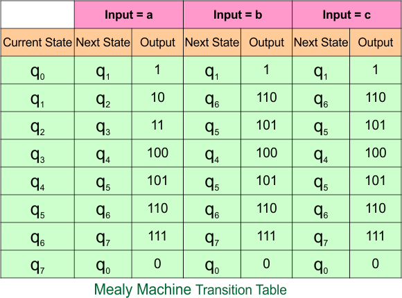
The explanation of the above Mealy Machine transition table is given below
In the current state “q0”,
- when the input is “a”, the next state remains “q1” and the output is “1”.
- When the input is “b”, the next state remains “q1” and the output is “1”.
- When the input is “c”, the next state remains “q1” and the output is “1”.
In the current state “q1”,
- when the input is “a”, the next state remains “q2” and the output is “10”.
- When the input is “b”, the next state remains “q6” and the output is “110”.
- When the input is “c”, the next state remains “q6” and the output is “110”.
In the current state “q2”,
- when the input is “a”, the next state remains “q3” and the output is “11”.
- When the input is “b”, the next state remains “q5” and the output is “101”.
- When the input is “c”, the next state remains “q5” and the output is “101”.
In the current state “q3”,
- when the input is “a”, the next state remains “q4” and the output is “100”.
- When the input is “b”, the next state remains “q4” and the output is “100”.
- When the input is “c”, the next state remains “q4” and the output is “100”.
In the current state “q4”,
- when the input is “a”, the next state remains “q5” and the output is “101”.
- When the input is “b”, the next state remains “q5” and the output is “101”.
- When the input is “c”, the next state remains “q5” and the output is “101”.
In the current state “q5”,
- when the input is “a”, the next state remains “q6” and the output is “110”.
- When the input is “b”, the next state remains “q6” and the output is “110”.
- When the input is “c”, the next state remains “q6” and the output is “110”.
In the current state “q6”,
- when the input is “a”, the next state remains “q7” and the output is “111”.
- When the input is “b”, the next state remains “q7” and the output is “111”.
- When the input is “c”, the next state remains “q7” and the output is “111”.
In the current state “q7”,
- when the input is “a”, the next state remains “q0” and the output is “0”.
- When the input is “b”, the next state remains “q0” and the output is “0”.
- When the input is “c”, the next state remains “q0” and the output is “0”.
Example 8.4: 8-States, 4-Input Symbol
Moore Machine
Here is the Moore Machine, which contains a seven-state (“q0”, “q1”, “q2”, “q3”, “q4”, “q5”, “q6” and “q7”) with outputs (“0”, “1”, “10”, “11”, “100”, “101”, “110”, and “111”) and two input symbols (“a”, “b”, “c”, and “d”). We will convert it into a corresponding Mealy machine.
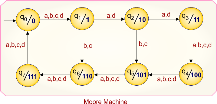
Moore Machine Transition Table
Here is the transition table for the given Moore machine
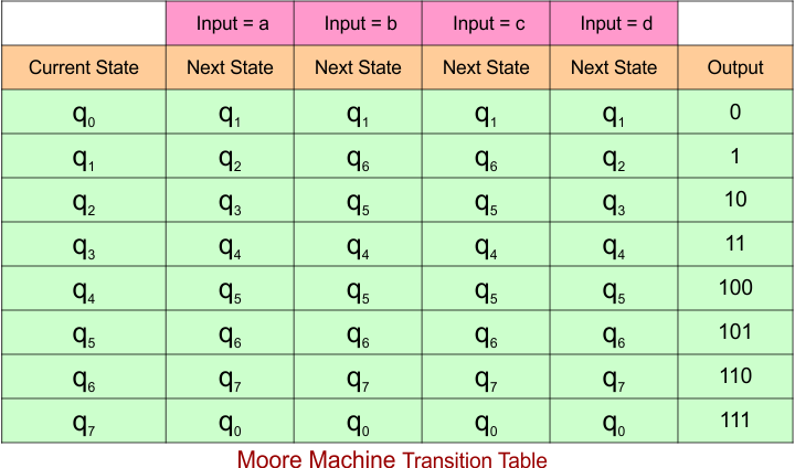
The explanation of the above Mealy Machine transition table is given below
At the current state “q0”,
- When the input is “a”, the next state remains “q1” and the output is “0”.
- When the input is “b”, the next state remains “q1” and the output is “0”.
- When the input is “c”, the next state remains “q1” and the output is “0”.
- When the input is “d”, the next state remains “q1” and the output is “0”.
At the current state “q1”,
- when the input is “a”, the next state remains “q2” and the output is “1”.
- When the input is “b”, the next state remains “q6” and the output is “1”.
- When the input is “c”, the next state remains “q6” and the output is “1”.
- When the input is “d”, the next state remains “q2” and the output is “1”.
At the current state “q2”,
- when the input is “a”, the next state remains “q3” and the output is “10”.
- When the input is “b”, the next state remains “q5” and the output is “10”.
- When the input is “c”, the next state remains “q5” and the output is “10”.
- When the input is “d”, the next state remains “q3” and the output is “10”.
At the current state “q3”,
- when the input is “a”, the next state remains “q4” and the output is “11”.
- When the input is “b”, the next state remains “q4” and the output is “11”.
- When the input is “c”, the next state remains “q4” and the output is “11”.
- When the input is “d”, the next state remains “q4” and the output is “11”.
At the current state “q4”,
- when the input is “a”, the next state remains “q5” and the output is “100”.
- When the input is “b”, the next state remains “q5” and the output is “100”.
- When the input is “c”, the next state remains “q5” and the output is “100”.
- When the input is “d”, the next state remains “q5” and the output is “100”.
At the current state “q5”,
- when the input is “a”, the next state remains “q6” and the output is “101”.
- When the input is “b”, the next state remains “q6” and the output is “101”.
- When the input is “c”, the next state remains “q6” and the output is “101”.
- When the input is “d”, the next state remains “q6” and the output is “101”.
At the current state “q6”,
- when the input is “a”, the next state remains “q7” and the output is “110”.
- When the input is “b”, the next state remains “q7” and the output is “110”.
- When the input is “c”, the next state remains “q7” and the output is “110”.
- When the input is “d”, the next state remains “q7” and the output is “110”.
At the current state “q7”,
- when the input is “a”, the next state remains “q0” and the output is “111”.
- When the input is “b”, the next state remains “q0” and the output is “111”.
- When the input is “c”, the next state remains “q0” and the output is “111”.
- When the input is “d”, the next state remains “q0” and the output is “111”.
Mealy Machine
According to the rule of Moore to Mealy conversion, the corresponding Mealy machine is given below,
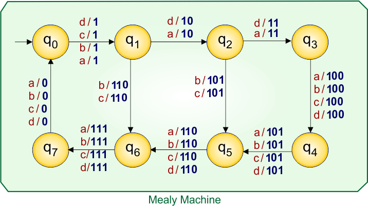
Let’s explain the Moore to Mealy conversion process
At state “q0”:
- For input “a”, the Moore machine moves to state “q1”, and since “q1” gives output “1”, the corresponding Mealy machine transition (over arrow) is written as a/1.
- For input “b”, the Moore machine moves to state “q1”, and since “q1” gives output “1”, the corresponding Mealy machine transition (over arrow) is written as b/1.
- For input “c”, the Moore machine moves to state “q1”, and since “q1” gives output “1”, the corresponding Mealy machine transition (over arrow) is written as c/1.
- For input “d”, the Moore machine moves to state “q1”, and since “q1” gives output “1”, the corresponding Mealy machine transition (over arrow) is written as d/1.
At state “q1”:
- For input “a”, the Moore machine moves to state “q2”, and since “q2” gives output “10”, the corresponding Mealy machine transition (over arrow) is written as a/10.
- For input “b”, the Moore machine moves to state “q6”, and since “q6” gives output “110”, the corresponding Mealy machine transition (over arrow) is written as b/110.
- For input “c”, the Moore machine moves to state “q6”, and since “q6” gives output “110”, the corresponding Mealy machine transition (over arrow) is written as c/110.
- For input “d”, the Moore machine moves to state “q2”, and since “q2” gives output “10”, the corresponding Mealy machine transition (over arrow) is written as d/10.
At state “q2”:
- For input “a”, the Moore machine moves to state “q3”, and since “q3” gives output “11”, the corresponding Mealy machine transition (over arrow) is written as a/11.
- For input “b”, the Moore machine moves to state “q5”, and since “q5” gives output “101”, the corresponding Mealy machine transition (over arrow) is written as b/101.
- For input “c”, the Moore machine moves to state “q5”, and since “q5” gives output “101”, the corresponding Mealy machine transition (over arrow) is written as c/101.
- For input “d”, the Moore machine moves to state “q3”, and since “q3” gives output “11”, the corresponding Mealy machine transition (over arrow) is written as d/11.
At state “q3”:
- For input “a”, the Moore machine moves to state “q4”, and since “q4” gives output “100”, the corresponding Mealy machine transition (over arrow) is written as a/100.
- For input “b”, the Moore machine moves to state “q4”, and since “q4” gives output “100”, the corresponding Mealy machine transition (over arrow) is written as b/100.
- For input “c”, the Moore machine moves to state “q4”, and since “q4” gives output “100”, the corresponding Mealy machine transition (over arrow) is written as c/100.
- For input “d”, the Moore machine moves to state “q4”, and since “q4” gives output “100”, the corresponding Mealy machine transition (over arrow) is written as d/100.
At state “q4”:
- For input “a”, the Moore machine moves to state “q5”, and since “q5” gives output “101”, the corresponding Mealy machine transition (over arrow) is written as a/101.
- For input “b”, the Moore machine moves to state “q5”, and since “q5” gives output “101”, the corresponding Mealy machine transition (over arrow) is written as b/101.
- For input “c”, the Moore machine moves to state “q5”, and since “q5” gives output “101”, the corresponding Mealy machine transition (over arrow) is written as c/101.
- For input “d”, the Moore machine moves to state “q5”, and since “q5” gives output “101”, the corresponding Mealy machine transition (over arrow) is written as d/101.
At state “q5”:
- For input “a”, the Moore machine moves to state “q6”, and since “q6” gives output “110”, the corresponding Mealy machine transition (over arrow) is written as a/110.
- For input “b”, the Moore machine moves to state “q6”, and since “q6” gives output “110”, the corresponding Mealy machine transition (over arrow) is written as b/110.
- For input “c”, the Moore machine moves to state “q6”, and since “q6” gives output “110”, the corresponding Mealy machine transition (over arrow) is written as c/110.
- For input “d”, the Moore machine moves to state “q6”, and since “q6” gives output “110”, the corresponding Mealy machine transition (over arrow) is written as d/110.
At state “q6”:
- For input “a”, the Moore machine moves to state “q7”, and since “q7” gives output “111”, the corresponding Mealy machine transition (over arrow) is written as a/111.
- For input “b”, the Moore machine moves to state “q7”, and since “q7” gives output “111”, the corresponding Mealy machine transition (over arrow) is written as b/111.
- For input “c”, the Moore machine moves to state “q7”, and since “q7” gives output “111”, the corresponding Mealy machine transition (over arrow) is written as c/111.
- For input “d”, the Moore machine moves to state “q7”, and since “q7” gives output “111”, the corresponding Mealy machine transition (over arrow) is written as d/111.
At state “q7”:
- For input “a”, the Moore machine moves to state “q0”, and since “q0” gives output “0”, the corresponding Mealy machine transition (over arrow) is written as a/0.
- For input “b”, the Moore machine moves to state “q0”, and since “q0” gives output “0”, the corresponding Mealy machine transition (over arrow) is written as b/0.
- For input “c”, the Moore machine moves to state “q0”, and since “q0” gives output “0”, the corresponding Mealy machine transition (over arrow) is written as c/0.
- For input “d”, the Moore machine moves to state “q0”, and since “q0” gives output “0”, the corresponding Mealy machine transition (over arrow) is written as d/0.
Mealy Machine Transition Table
The transition table of the above Mealy machine is given below
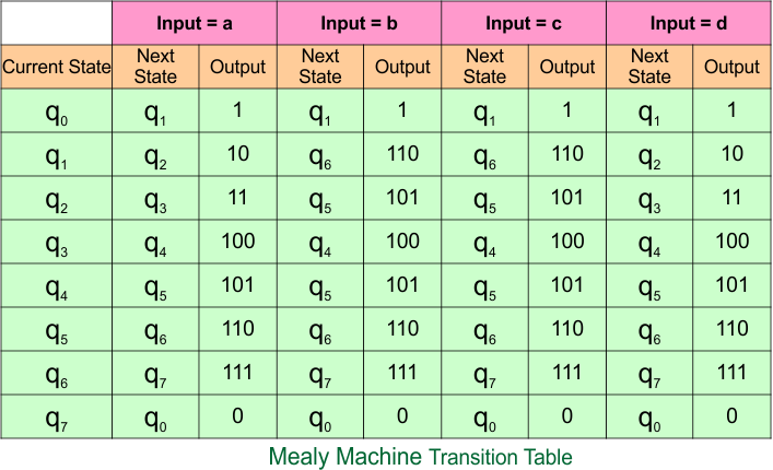
The explanation of the above Mealy Machine transition table is given below
In the current state “q0”,
- when the input is “a”, the next state remains “q1” and the output is “1”.
- When the input is “b”, the next state remains “q1” and the output is “1”.
- When the input is “c”, the next state remains “q1” and the output is “1”.
- When the input is “d”, the next state remains “q1” and the output is “1”.
In the current state “q1”,
- when the input is “a”, the next state remains “q2” and the output is “10”.
- When the input is “b”, the next state remains “q6” and the output is “110”.
- When the input is “c”, the next state remains “q6” and the output is “110”.
- when the input is “d”, the next state remains “q2” and the output is “10”.
In the current state “q2”,
- when the input is “a”, the next state remains “q3” and the output is “11”.
- When the input is “b”, the next state remains “q5” and the output is “101”.
- When the input is “c”, the next state remains “q5” and the output is “101”.
- When the input is “d”, the next state remains “q3” and the output is “11”.
In the current state “q3”,
- when the input is “a”, the next state remains “q4” and the output is “100”.
- When the input is “b”, the next state remains “q4” and the output is “100”.
- When the input is “c”, the next state remains “q4” and the output is “100”.
- When the input is “d”, the next state remains “q4” and the output is “100”.
In the current state “q4”,
- when the input is “a”, the next state remains “q5” and the output is “101”.
- When the input is “b”, the next state remains “q5” and the output is “101”.
- When the input is “c”, the next state remains “q5” and the output is “101”.
- When the input is “d”, the next state remains “q5” and the output is “101”.
In the current state “q5”,
- when the input is “a”, the next state remains “q6” and the output is “110”.
- When the input is “b”, the next state remains “q6” and the output is “110”.
- When the input is “c”, the next state remains “q6” and the output is “110”.
- When the input is “d”, the next state remains “q6” and the output is “110”.
In the current state “q6”,
- when the input is “a”, the next state remains “q7” and the output is “111”.
- When the input is “b”, the next state remains “q7” and the output is “111”.
- When the input is “c”, the next state remains “q7” and the output is “111”.
- When the input is “d”, the next state remains “q7” and the output is “111”.
In the current state “q7”,
- when the input is “a”, the next state remains “q0” and the output is “0”.
- When the input is “b”, the next state remains “q0” and the output is “0”.
- When the input is “c”, the next state remains “q0” and the output is “0”.
- When the input is “d”, the next state remains “q0” and the output is “0”.
Moore to Mealy Conversion Questions
Question 01: 1’s complement
Construct a Moore Machine and convert that Moore machine to an equivalent Mealy Machine that generates the 1’s complement of a given binary number.
Solution
Here is a Moore machine to Mealy conversion Transition diagram for a given example 04 to generate the 1’s complement of a given binary number.
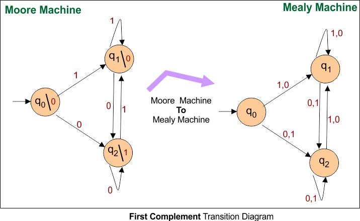
Here is a Moore machine to Mealy conversion Transition Table for a given example 04 to generate the 1’s complement of a given binary number.
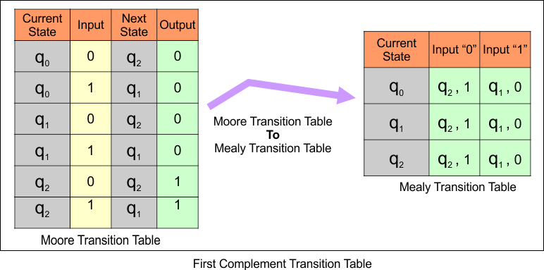
Question 02: 2nd Complement
Construct a Moore Machine and convert that Moore machine to an equivalent Mealy Machine that generates the 2nd complement of a given binary number.
Solution
Here is a Moore machine to Mealy conversion Transition diagram for a given example to generate the 2nd complement of a given binary number.
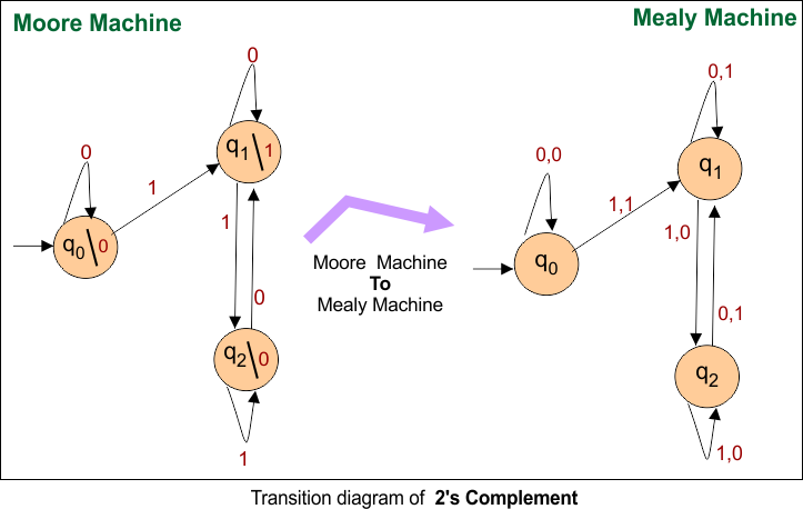
Here is a Moore machine to Mealy conversion Transition Table for a given example to generate the 2nd complement of a given binary number.
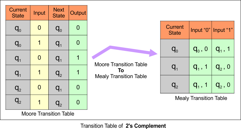
Question 03: Prints “a” whenever the sequence “01”
Construct a Moore Machine and convert that Moore machine to an equivalent Mealy Machine that prints “a” whenever the sequence “01” is encountered in any input binary string.
Solution
Here is a Moore machine to Mealy conversion Transition diagram for a given example that prints “a” whenever the sequence “01” is encountered in any input binary string.
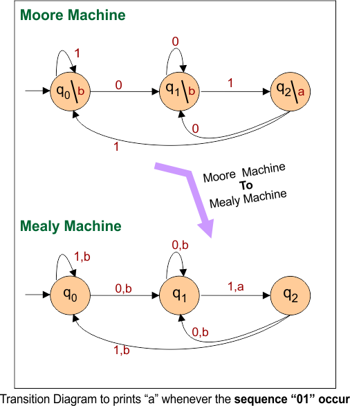
Here is a Moore machine to Mealy conversion Transition Table for a given example that prints “a” whenever the sequence “01” is encountered in any input binary string.
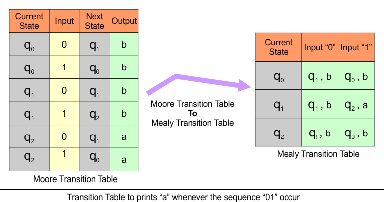
Question 04: Counts the number of a’s
Construct a Moore Machine and convert that Moore machine to an equivalent Mealy Machine that takes all the strings of a’s and b’s as input and counts the number of a’s in the input string in terms of 1. Where
input Σ = {a,b}, and output △ = {0,1}
Solution
Here is a Moore machine to Mealy conversion Transition diagram for a given example that takes all the strings of a’s and b’s as input and counts the number of a’s in the input string in terms of 1 over input Σ = {a,b}, and output △ = {0,1}.
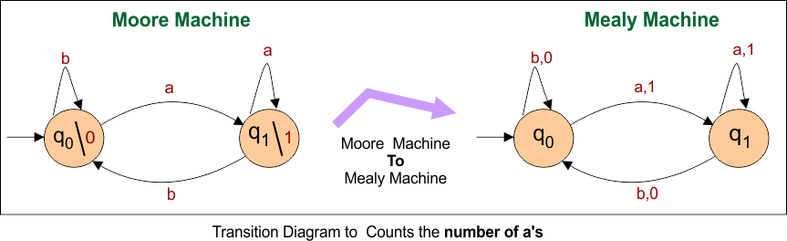
Here is a Moore machine to Mealy conversion Transition table for a given example that takes all the strings of a’s and b’s as input and counts the number of a’s in the input string in terms of 1 over input Σ = {a,b}, and output △ = {0,1}.
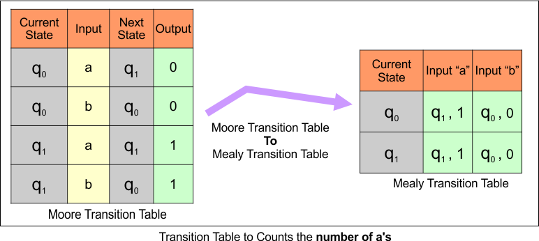
Question 05: Counts the occurrences of the sequence “abb”
Construct a Moore Machine and convert that Moore machine to an equivalent Mealy Machine that counts the occurrences of the sequence “abb” In any input string over
input Σ = {a,b}, output △ = {0,1}
Solution
Here is a Moore machine to Mealy conversion Transition diagram for a given example that counts the occurrences of the sequence “abb” In any input string over
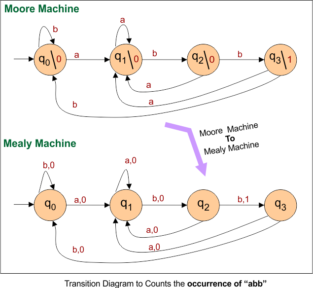
Here is a Moore machine to Mealy conversion Transition Table for a given example that counts the occurrences of the sequence “abb” In any input string over

Here is a Moore machine to Mealy conversion Transition Table for a given example 04 to generate the 1’s complement of a given binary number.
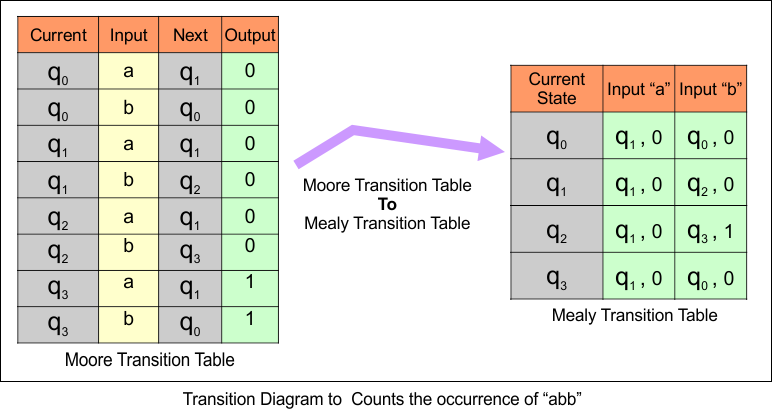
Question 06: Counts the occurrences of the sequence “0101”
Construct a Moore Machine and convert that Moore machine to an equivalent Mealy Machine that counts the occurrences of the sequence “0101” In any input string over {0,1}
Input Σ = {0,1}, Output △ = {0,1}
Solution
Here is a Moore machine to Mealy conversion Transition diagram for a given example that counts the occurrences of the sequence “0101”
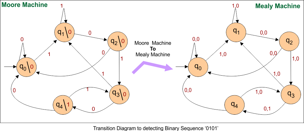
Here is a Moore machine to Mealy conversion Transition Table for a given example that counts the occurrences of the sequence “0101”
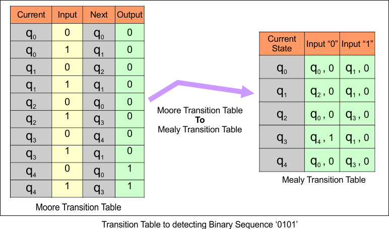
Question 07: “A” as output if input ends with “10”, “B” as output if input ends with “11”, otherwise gives C as output.
Construct a Moore Machine and convert that Moore machine to an equivalent Mealy Machine that takes a set of all strings over {0,1} and gives
- “A” as output if input ends with “10”
- “B” as output if input ends with “11”
- Otherwise gives C as output.
Input Σ = {0,1}, Output △ = {A,B,C}
Solution
Here is a Moore machine to Mealy conversion Transition diagram for a given example that takes a set of all strings over {0,1} and gives
- “A” as output if input ends with “10”
- “B” as output if input ends with “11”
- Otherwise gives C as output.
Input Σ = {0,1}, Output △ = {A,B,C}
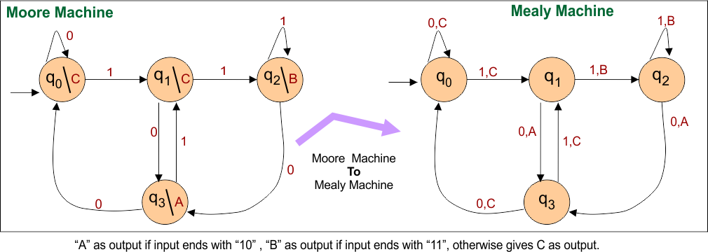
Here is a Moore machine to Mealy conversion Transition Table for a given example is given below
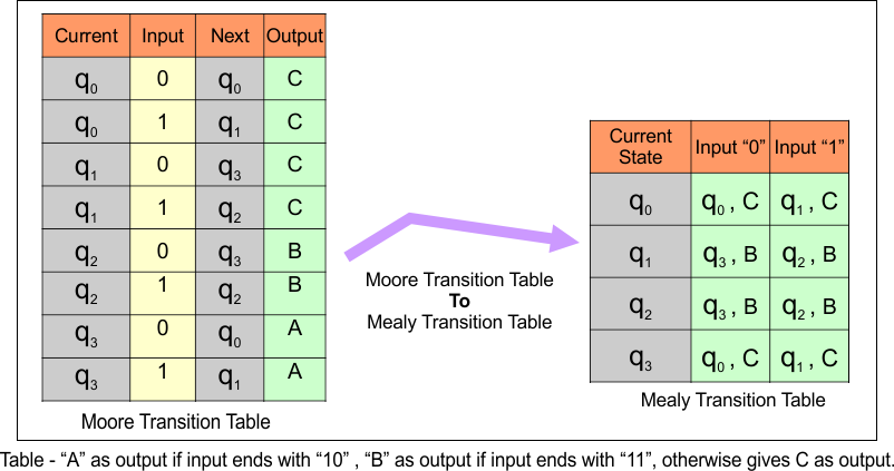
Question 08: If the input substring is 101, the machine outputs A. If the input has a substring 110, its output is B; Otherwise, it outputs C.
Construct a Moore Machine and convert that Moore machine to an equivalent Mealy Machine that takes a binary input sequence, such that if it has a
- Substring 101, the machine output A,
- If the input has a substring 110, its output is B;
- Otherwise, it outputs C.
Input Σ = {0,1}, Output △ = {A,B,C}
Solution
Here is a Moore machine to Mealy conversion Transition diagram for a given example that takes a binary input sequence, such that if it has a
- Substring 101, the machine output A,
- If the input has a substring 110, its output is B;
- Otherwise, it outputs C.
Input Σ = {0,1}, Output △ = {A,B,C}
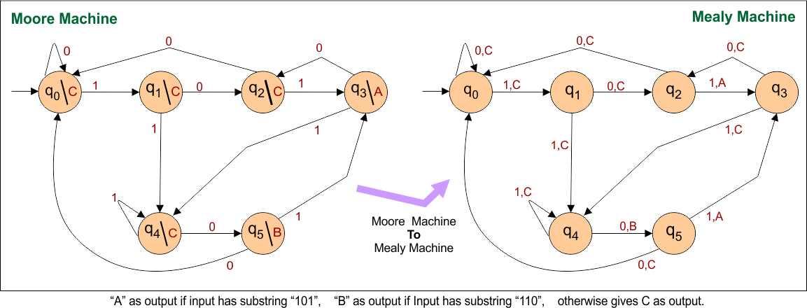
Here is a Moore machine to Mealy conversion Transition Table for a given example
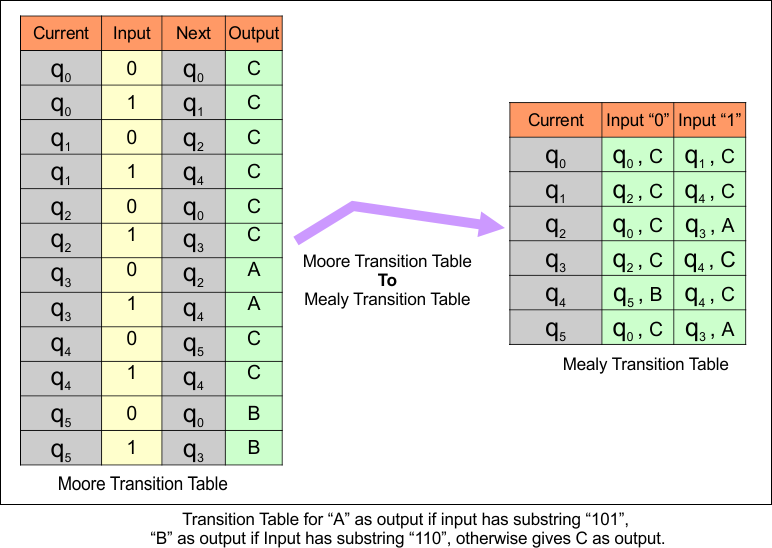
Question 09: Generates the remainder after dividing a number by 3
Construct a Moore Machine and convert that Moore machine to an equivalent Mealy Machine that generates the remainder after dividing a number by 3 (modulus of 3) in binary
over Σ = {0,1}, △ = {0,1,2}
Solution
Here is a Moore machine to Mealy conversion Transition diagram for a given example that generates the remainder after dividing a number by 3 (modulus of 3) in binary over Σ = {0,1}, △ = {0,1,2}
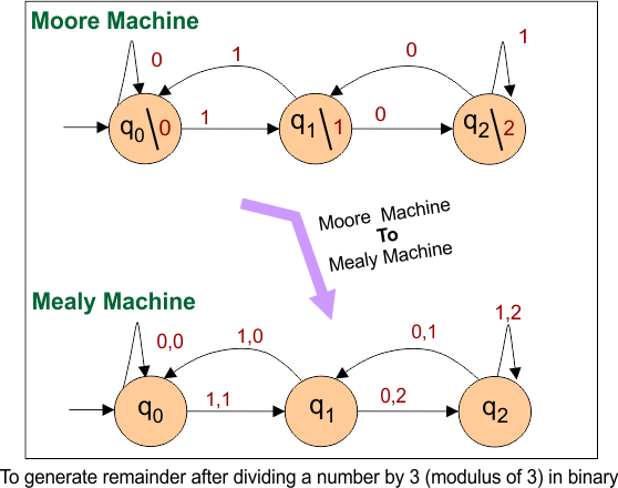
Here is a Moore machine to Mealy conversion Transition Table for a given example that generates the remainder after dividing a number by 3 (modulus of 3) in binary over Σ = {0,1}, △ = {0,1,2}
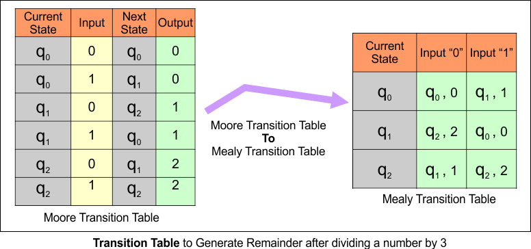
Question 10: Generates the remainder after dividing a number by 4
Construct a Moore Machine and convert that Moore machine to an equivalent Mealy Machine that generates the remainder after dividing a number by 4 (modulus of 4) in binary
over Σ = {0,1}, △ = {0,1,2,3}
Solution
Here is a Moore machine to Mealy conversion Transition diagram for a given example that generates the remainder after dividing a number by 4 (modulus of 4) in binary over Σ = {0,1}, △ = {0,1,2,3}
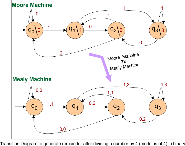
Here is a Moore machine to Mealy conversion Transition Table for a given example that generates the remainder after dividing a number by 4 (modulus of 4) in binary over Σ = {0,1}, △ = {0,1,2,3}
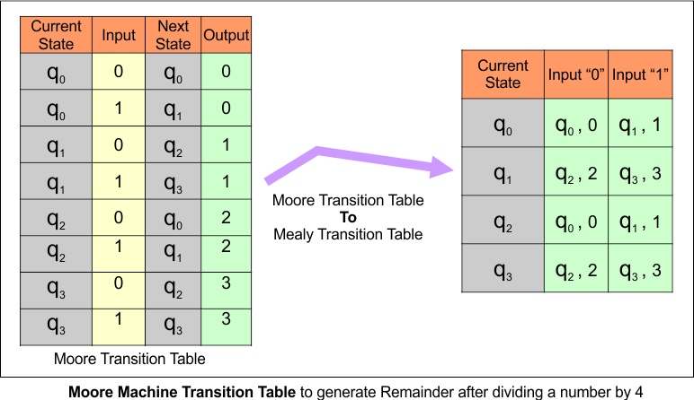
Question 11: Generates the remainder after dividing a number by 5
Construct a Moore Machine and convert that Moore machine to an equivalent Mealy Machine that generates the remainder after dividing a number by 5 (modulus of 5) in binary
over Σ = {0,1}, △ = {0,1,2,3,4}
Solution
Here is a Moore machine to Mealy conversion Transition diagram for a given example that generates the remainder after dividing a number by 5 (modulus of 5) in binary over Σ = {0,1}, △ = {0,1,2,3,4}
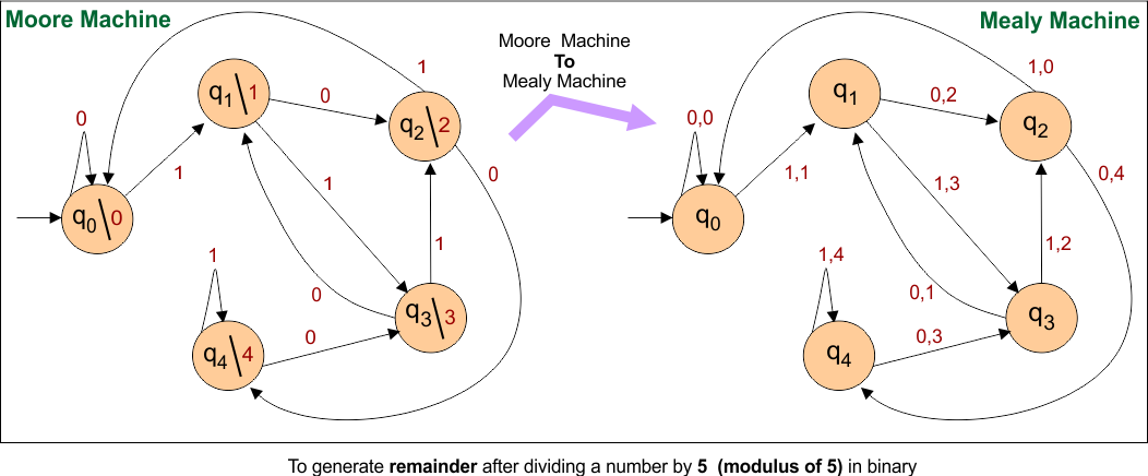
Here is a Moore machine to Mealy conversion Transition Table for a given example that generates the remainder after dividing a number by 5 (modulus of 5) in binary over Σ = {0,1}, △ = {0,1,2,3,4}
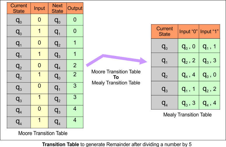
Moore to Mealy Conversion Process (Easy Way)
Consider the following Moore Machine
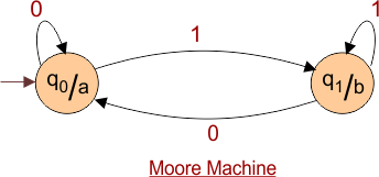
Solution
At q0 for input “0”, the transition also goes to the state q0, which gives output “a”. So for Mealy Machine, Just label output with input over arrow as given below.
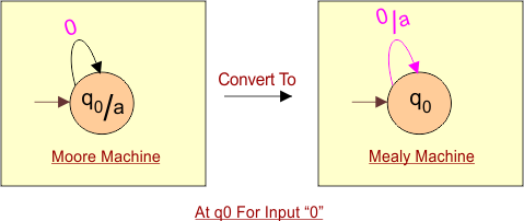
At q0 for input “1”, the transition also goes to the state q1, which gives output “b.” So for Mealy Machine, Just label output (b) with input (1) over the arrow as given below.
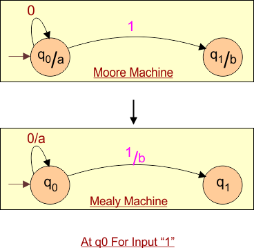
Now Move to q1 to discuss both inputs “0” and “1”.
The new state, At q1 for input “0”, the transition also goes to the state q1, which gives output “b.” So for Mealy Machine, Just label output (b) with input (1) over the arrow as given below.
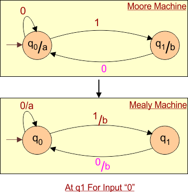
At q1 for input “1”, the transition goes to the state q0, which gives output “a.” So for Mealy Machine, Just label output (b) with input (0) over the arrow as given below.
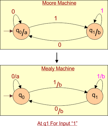
Hence in above diagram, the given Moore Machine is converted into corresponding Mealy Machine.
Key Changes When Converting Moore to Mealy
| Key | Change |
|---|---|
| Output placement | Moves from states to transitions |
| Output timing | Happens during transition, not after |
| State count | Can reduce (fewer states needed for different outputs) |
| Output function | Depends on the state and input, not just the state |
Important
Number of states
After conversion from Moore to the Mealy Machine, The states of the Mealy Machine are always less than or equal to the Moore Machine.
Transition Table
As discussed earlier in the Moore and Mealy Machine lectures, transition tables can also be obtained from corresponding Moore or Mealy diagrams.