


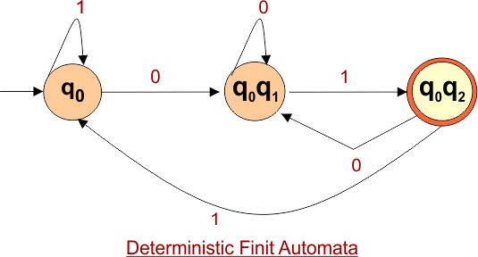
NFA to DFA Conversion
Conversion from NFA to DFA may provide the following results,
- The number of states in the resulting DFA may differ from that of the original NFA.
- The DFA can have a maximum of 2n states where “n” is the number of states in the NFA.
Generally, a relationship exists between the number of states in NFA and DFA.
1 <= n <= 2m
Where,
- n represents the number of states in the DFA
- m represents the number of states in the NFA
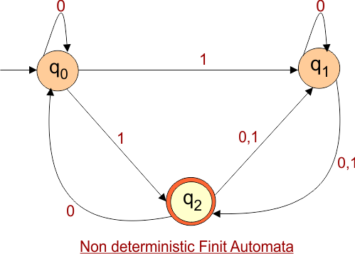
Every nondeterministic finite automaton (NFA) can be converted to a deterministic finite automaton (DFA).
NFA to DFA Conversion Algorithm
There are four basic steps for the conversion of NFA to DFA.
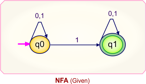
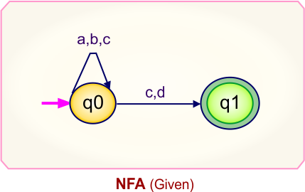
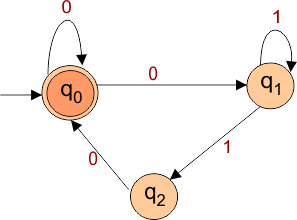
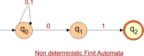
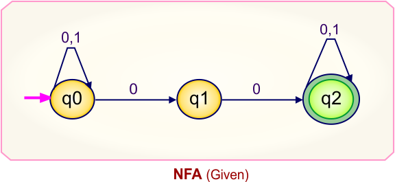
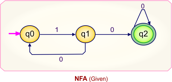
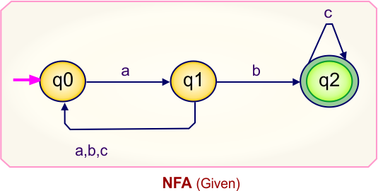
- Step 01: Draw an NFA graph (Mostly Given).
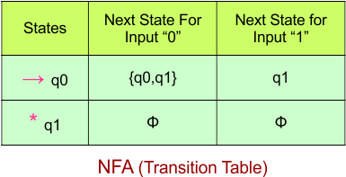
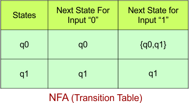
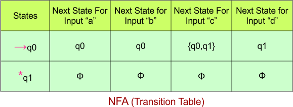
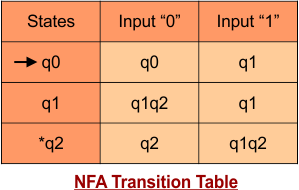
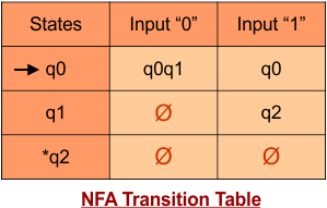
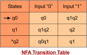
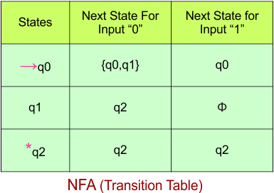
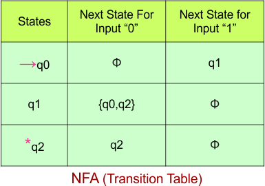
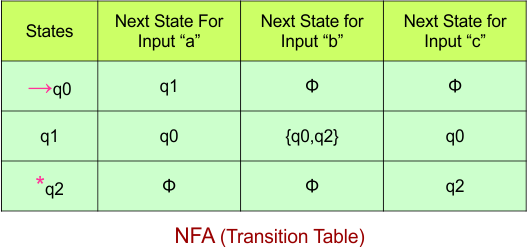
- Step 02: Draw the NFA transition table from the NFA diagram.
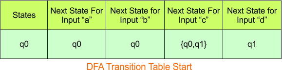
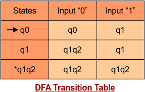
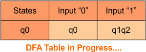
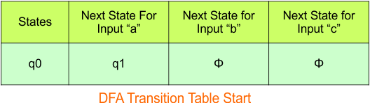
- Step 03: Convert the NFA transition table to the DFA transition Table.
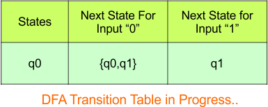
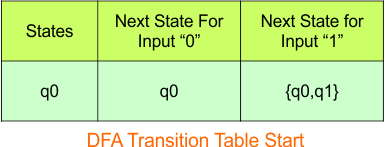
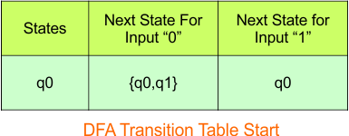
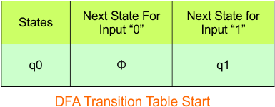
- Step 3.1: Select the first two rows of the NFA table to begin constructing the DFA. These two rows will now serve as the initial rows of the DFA.
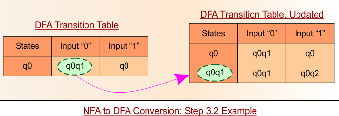
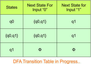
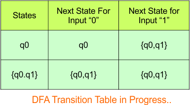
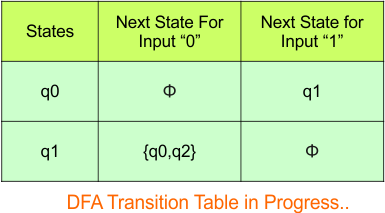
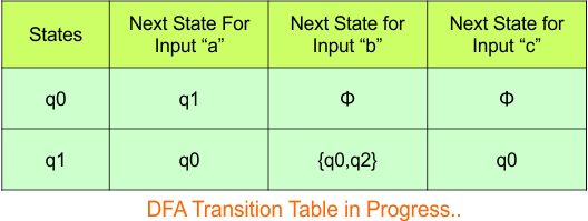
- Step 3.2: If any state appears in the input column of the DFA but is not found in the States column of the DFA, it is considered a New State. Simply copy this new state and puts in the states column and add its all possible transitions in the DFA table. The transitions for the New State in the DFA table will follow the NFA transition table. Repeat this procedure until no new states are found in the input columns.
- Step 3.3: If “x” was the final state in the NFA Transition Table, then all those states will be the final states in the DFA Transition Table where “x” exists.
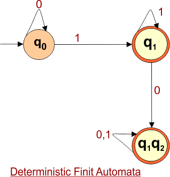
- Step 04: Convert the DFA table to the DFA Diagram.
Step 3.1 Purpose
|
NFA to DFA Algorithm: More Understanding
In the algorithm of NFA to DFA conversion, all other steps are straightforward except Steps 3.1 and 3.2. Here is a pictorial example of these two steps.
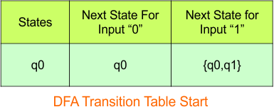
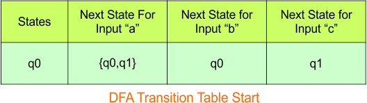
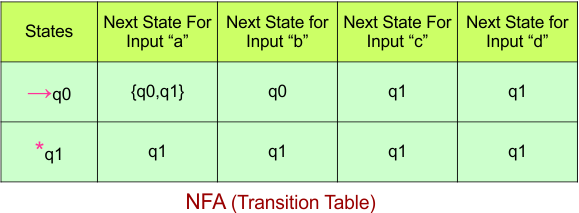
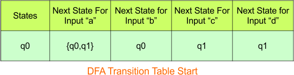
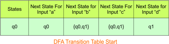
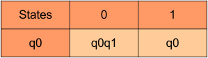
Step 3.1: Select the first two rows of the NFA table to begin constructing the DFA. These two rows will now serve as the initial rows of the DFA.

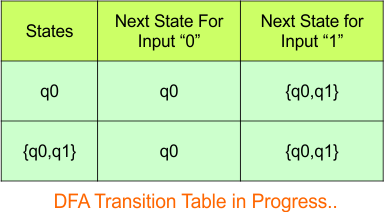
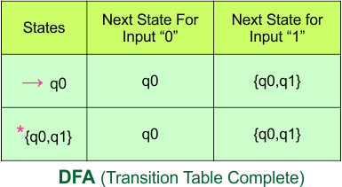
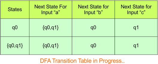
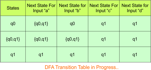
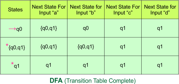
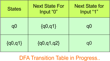
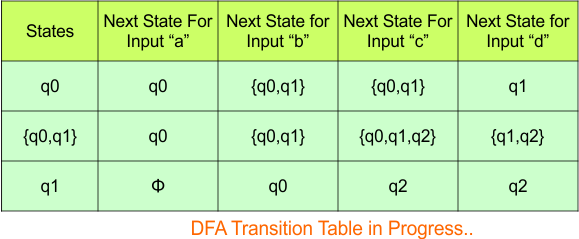
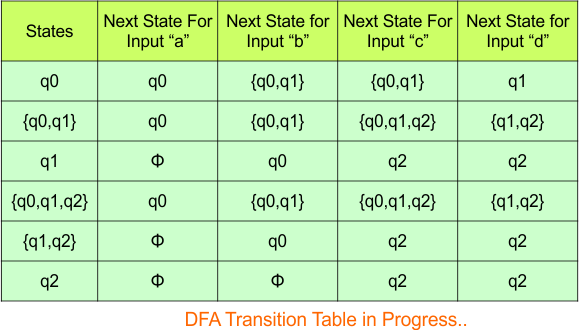
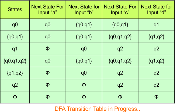
Step 3.2: In the following example, State “q0q1” is a new state because it is present in the input columns of the DFA but does not exist in the state column. Put “q0q1” in the state column along with its transitions.
Let’s discuss 50+ examples of NFA to DFA conversions of various categories, according to the algorithm discussed earlier in this lecture.
NFA to DFA Category-01 Examples: 2-States, 2-Input Symbols
Category 01 covers NFA to DFA conversions for machines with two states over the binary alphabet {0,1} or {a,b}. Each example explains the subset construction process step by step, including transition tables, composite states, and final state identification.
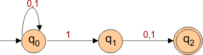
NFA to DFA Conversion Example 1.1
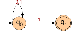
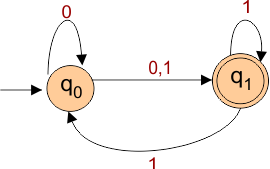
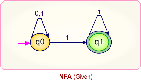
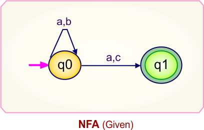
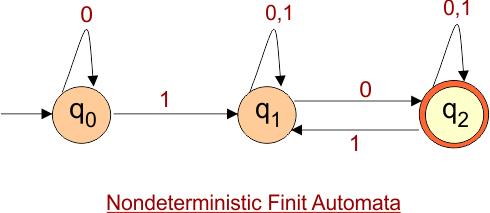
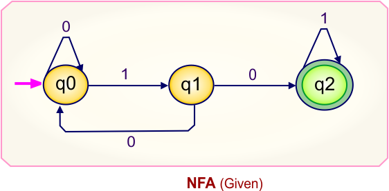
Step 01: Draw NFA Graph
The following is the NFA graph that needs to be converted to a DFA.

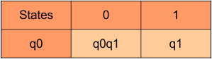
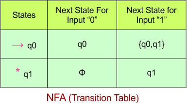
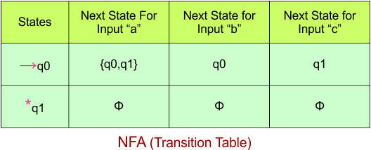
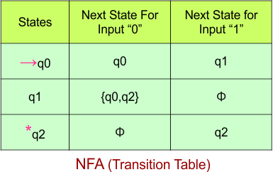
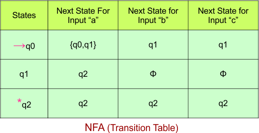
Step 02: Draw the NFA Transition Table.
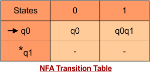
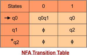
The following is the NFA transition table, which is derived from the given NFA.
Note: All transitions are made according to the NFA transition table to get the DFA transition table.
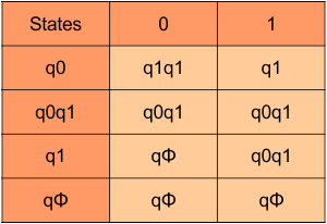
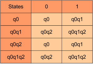
Step 03: Conversion of NFA to DFA Transition Table
Let’s start the conversion of the NFA transition table to the DFA transition Table.
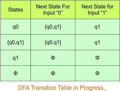
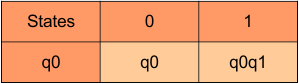
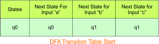
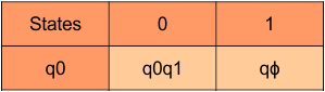
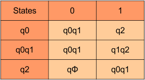
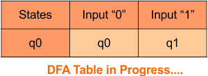
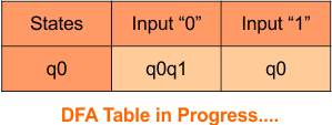
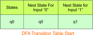
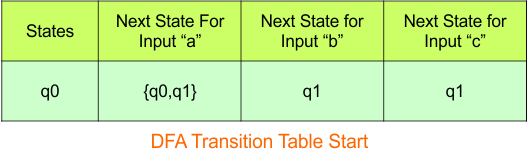
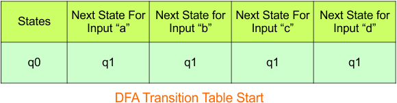
Step 3.1: Select the first two rows of the NFA transition table, which will become the first two rows of the DFA transition table given below.
In the above DFA Table
- State Column Contains: “q0”
- Input columns contains: “q0,q1”, “q1”
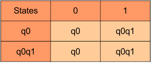
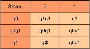
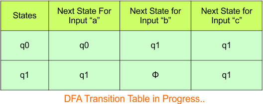
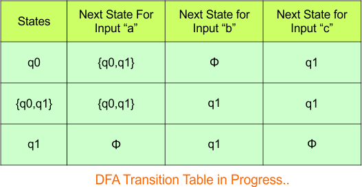
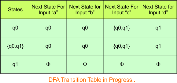
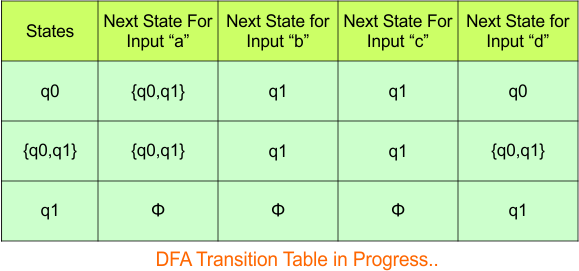
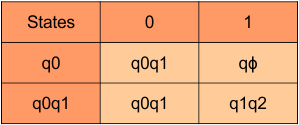
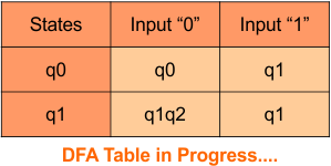
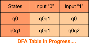
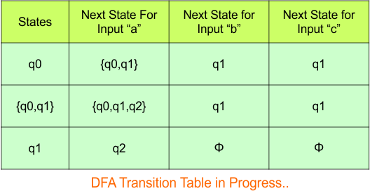
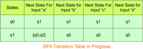
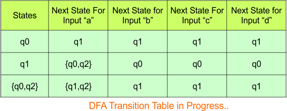
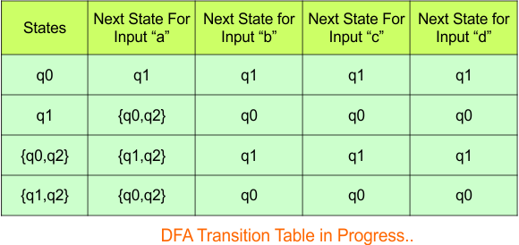
Step 3.2: States “q0q1” and “q1” are newly added because these states appear in the input columns of the DFA but do not exist in the state column. Include “q0q1” and “q1” in the state column along with their transitions.
Transition calculations for state “q0q1“
For input “0”
δ([q0q1], 0) = δ(q0, 0) ∪ δ(q1, 0)
= {q0q1} ∪ {ϕ}
= {q0q1}
For input “1”
δ([q0q1], 1) = δ(q0, 1) ∪ δ(q1, 1)
= {q1} ∪ {ϕ}
= {q1}
Transition calculations for state “q1“
For input “0”
δ([q1], 0) = {ϕ}
For input “1”
δ([q1], 1) = {ϕ}
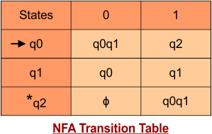
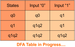
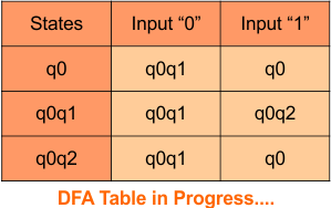
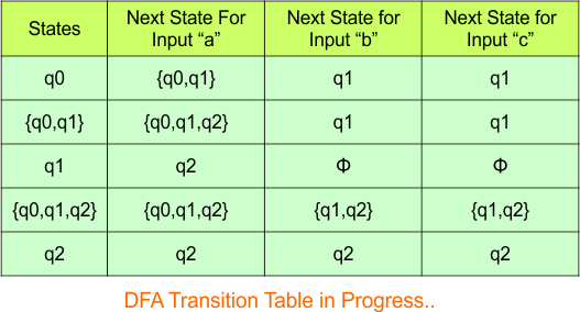
The updated DFA table is given below.
In the above DFA Table
- State Column Contains: “q0”, “q0q1”, “q1”
- Input columns contain: “q0”, “q0q1”, “q1”
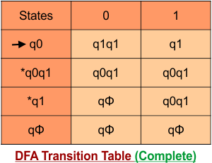
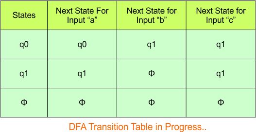
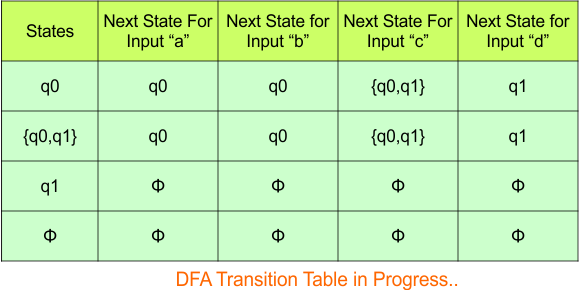
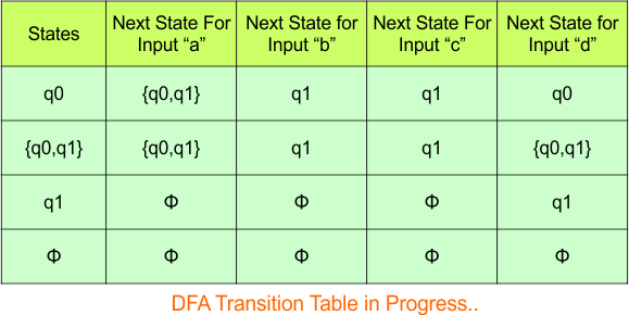
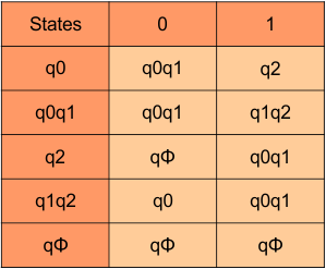
Repeat Step 3.2: No new state exists in the DFA table, except ϕ. Transition at “ϕ” against all inputs will always stay at “ϕ”. The updated DFA Table is given below
At this stage, no new state remains for the state column. The DFA table is one step away from being complete.
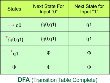
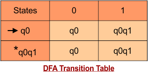
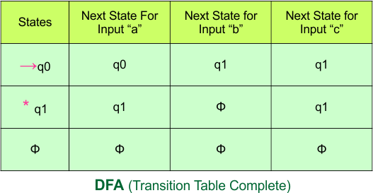
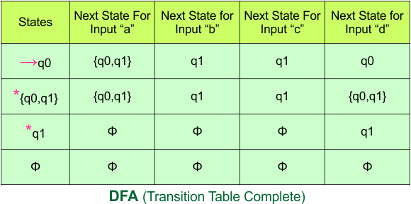
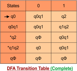
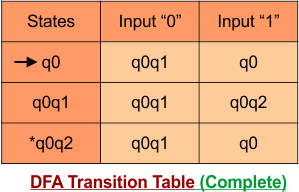
Step 3.3: State “q1” was the final state in the NFA Table. That’s why all those states will be the final states where “q1” is present in the DFA state column. Simply mark with “*” to represent the final state.
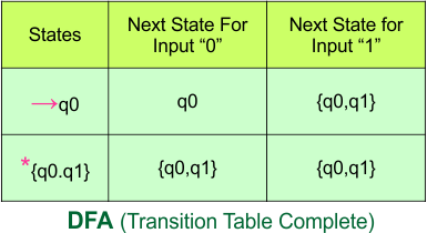
The following is the updated DFA table with all its final states
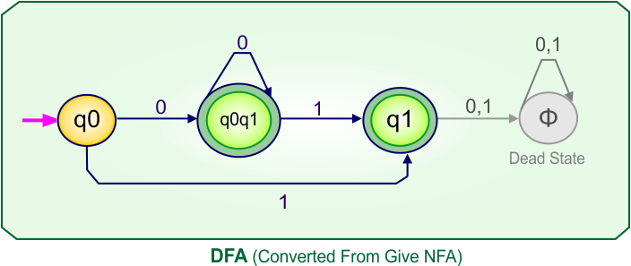
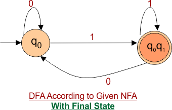
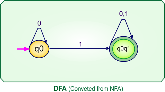
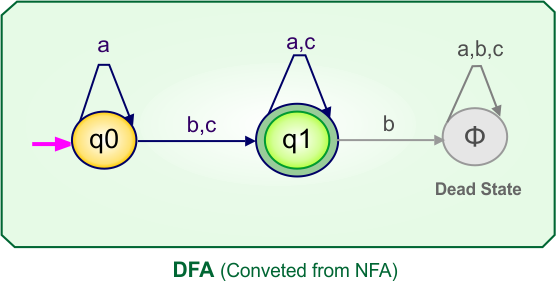
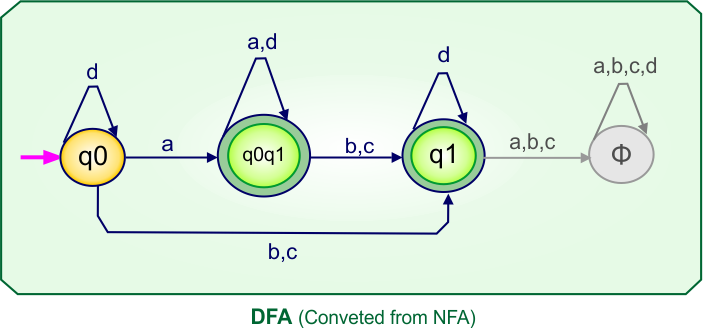
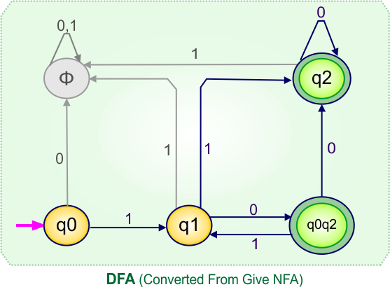
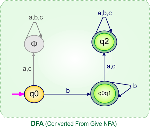
Step 4: Now draw the DFA according to the DFA transition table
The following is the converted DFA from the given NFA.
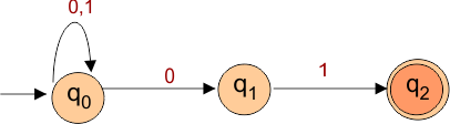
NFA to DFA Conversion Example 1.2
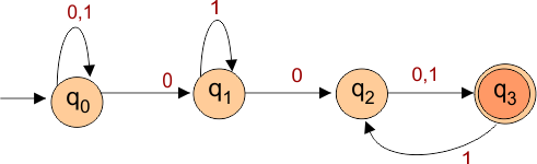
Problem: Draw an NFA that accepts all the strings ending with “1” over Σ {0,1} and convert this NFA to its corresponding DFA.
Step 01: Draw NFA Graph
The following is the NFA graph for conversion into DFA.
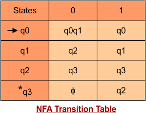
Step 02: Draw the NFA transition Table.
The NFA transition table of the above NFA is given below
Don’t confuse: dash (“-“) symbol represents the empty symbol (ϕ).
Step 03: Conversion of NFA to DFA Transition Table
Let’s start the conversion of the NFA transition table to the DFA transition Table.
Step 3.1: Select the first two rows of the NFA transition table, which will become the first two rows of the DFA transition table given below.
In the above DFA Table
- State Column Contains: “q0”
- Input columns contain: “q0”, “q0q1”
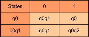
Step 3.2: State “q0q1” is a new state because it is present in the input columns of the DFA but does not exist in the state column. Put “q0q1” in the state column along with its transitions.
Transition calculations for state “q0q1”
For input “0”
δ([q0q1], 0) = δ(q0, 0) ∪ δ(q1, 0)
= {q0} ∪ {ϕ}
= {q0}
For input “1”
δ([q0q1], 1) = δ(q0, 1) ∪ δ(q1, 1)
= {q0q1} ∪ {ϕ}
= {q0q1}
The transition of state “q0q1” against input “0” is “q0”, and the transition against input “1” is “q0q1”. Hence, the updated DFA table is given below.
In the above DFA Table
- State Column Contains: “q0”, “q0q1”
- Input columns contain: “q0”, “q0q1”
At this stage, no new state remains. The DFA table is one step away to complete.
Step 3.3: State “q1” was the final state in the NFA Table. That’s why all those states will be the final states where “q1” is present in the DFA state column. Simply mark with “*” to represent the final state.
Here is the complete DFA transition table with its final states
Step 4: Draw DFA
Draw a DFA according to the DFA transition table. The DFA transition table contains two states (q0, q0q1) in its state column. Thus, the desired DFA machine graph will contain these states, and transitions will be made according to the DFA transition table.
NFA to DFA Conversion Example 1.3
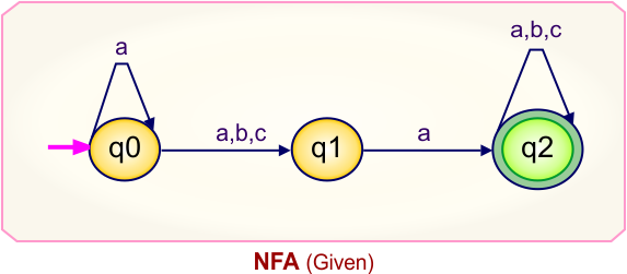
Step 01: Draw NFA Graph
The following is the NFA graph that needs to be converted to a DFA.
Step 02: Draw the NFA Transition Table.
The following is the NFA transition table which is derived from the given NFA.

Note: All transitions are made according to the NFA transition table to get the DFA transition table.
Step 03: Conversion of NFA to DFA Transition Table
Let’s start the conversion of the NFA transition table to the DFA transition Table.
Step 3.1: Select the first two rows of the NFA transition table, which will become the first two rows of the DFA transition table given below.
In the above DFA Table
- State Column Contains: “q0”
- Input columns contain: “q0”, “q0q1”
Step 3.2: State “q0q1” is a new state because it is present in the input columns of the DFA but does not exist in the state column. Put “q0q1” in the state column along with its transitions.
Transition calculations for state “q0q1”
For input “0”
δ([q0q1], 0) = δ(q0, 0) ∪ δ(q1, 0)
= {q0q1} ∪ {ϕ}
= {q0q1}
For input “1”
δ([q0q1], 1) = δ(q0, 1) ∪ δ(q1, 1)
= {q1} ∪ {q0q1}
= {q0q1}
The transition of state “q0q1” against input “0” is “q0q1”, and the transition against input “1” is “q0q1”. Hence, the updated DFA table is given below.

In the above DFA Table
- State Column Contains: “q0”, “q0q1”
- Input columns contain: “q0q1”, “q1”
Repeat Step 3.2: “q1” is a new state because it is present in the input columns of the DFA but does not exist in the state column. Put “q1” in the state column along with their transitions.
Transition calculations for state “q1”
For input “0”
δ([q1], 0) = {qϕ}
For input “1”
δ([q1], 1) = {q0q1}
The transition of state “q1” against input “0” is “qϕ“, and the transition against input “1” is “q0q1“. Hence, the updated DFA table is given below.
In the above DFA Table
- State Column Contains: “q0”, “q0q1”, “q1”
- Input columns contain: “q0q1”, “q1”, “qϕ“
Repeat Step 3.2: “qϕ” is a new state because it is present in the input columns of the DFA but does not exist in the state column. Put “qϕ” in the state column along with their transitions.
Transition calculations for state “qϕ”
For input “0”
δ([qϕ], 0) = {qϕ}
For input “1”
δ([qϕ], 1) = {qϕ}
The transition of state “qϕ” against input “0” is “qϕ“, and the transition against input “1” is “qϕ“. Hence, the updated DFA table is given below.
In the above DFA Table
- State Column Contains: “q0”, “q0q1”, “q1”, “qϕ“
- Input columns contain: “q0q1”, “q1”, “qϕ“
At this stage, no new state remains for the state column. The DFA table is one step away to complete.
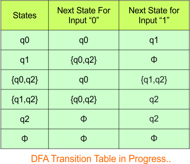
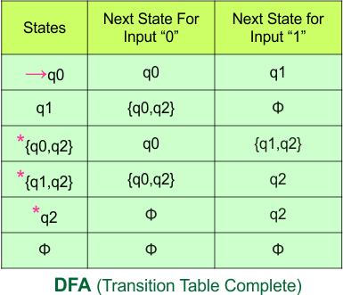
Step 3.3: State “q1” was the final state in the NFA Table. That’s why all those states will be the final states where “q2” is present in the DFA state column. Simply mark with “*” to represent the final state.
The following is the updated DFA table with all its final states
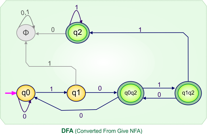
Step 4: Now draw DFA according to the DFA transition table
The following is the converted DFA from the given NFA.

NFA to DFA Conversion Example 1.4
Step 01: Draw NFA Graph
The graph below represents an NFA that needs conversion into a DFA.
Step 02: Draw the NFA Transition Table.
The table below presents the transition table of the NFA derived from the given NFA.
Step 03: Conversion of NFA to DFA Transition Table
Let’s begin converting the NFA transition table to the DFA transition table.
Step 3.1: Select the first two rows of the NFA transition table to form the initial two rows of the DFA transition table below.
In the above DFA Table
- State Column Contains: “q0”
- Input columns contain: “q0”, “q0q1”
Step 3.2: State “q0q1” is a new state because it appears in the DFA’s input columns but does not exist in the state column. Add “q0q1” to the state column along with its transitions.
Transition calculations at state “q0q1”
For input “0”
δ([q0q1], 0) = δ(q0, 0) ∪ δ(q1, 0)
= {q0} ∪ {ϕ}
= {q0}
For input “1”
δ([q0q1], 1) = δ(q0, 1) ∪ δ(q1, 1)
= {q0q1} ∪ {q1}
= {q0q1}
The updated DFA table is given below.
At this stage, no new states remain for the state column. The DFA table is just one step away from completion.
Step 3.3: State “q1” was the final state in the NFA table. Therefore, all states will be final states where “q1” appears in the DFA state column. Simply mark these states with “*” to indicate they are final states.
Here is the updated DFA table, which includes all of its final states.
Step 4: Now draw the DFA according to the DFA transition table
The following is the converted Deterministic Finite Automaton (DFA) derived from the given Nondeterministic Finite Automaton (NFA).
NFA to DFA Conversion Example 1.5
Step 01: Draw NFA Graph
The graph below represents an NFA that needs conversion into a DFA.
Step 02: Draw the NFA Transition Table.
The table below presents the transition table of the NFA derived from the given NFA.
Step 03: Conversion of NFA to DFA Transition Table
Let’s begin converting the NFA transition table to the DFA transition table.
Step 3.1: Select the first two rows of the NFA transition table to form the initial two rows of the DFA transition table below.
In the above DFA Table
- State Column Contains: “q0”
- Input columns contain: “q0”, “q0q1”
Step 3.2: State “q0q1” is a new state because it appears in the input columns of the DFA but does not exist in the state column. Add “q0q1” to the state column along with its transitions.
Transition calculations at state “q0q1”
For input “0”
δ([q0q1], 0) = δ(q0, 0) ∪ δ(q1, 0)
= {q0} ∪ {q1}
= {q0q1}
For input “1”
δ([q0q1], 1) = δ(q0, 1) ∪ δ(q1, 1)
= {q0q1} ∪ {q1}
= {q0q1}
The updated DFA table is given below.
In the above DFA Table
- State Column Contains: “q0”, “q0q1”
- Input columns contain: “q0”, “q0q1”
At this stage, no new states remain for the state column. The DFA table is just one step away from completion.
Step 3.3: State “q1” was the final state in the NFA table. Therefore, all states will be final states where “q1” appears in the DFA state column. Simply mark these states with “*” to indicate they are final states.
Here is the updated DFA table, which includes all of its final states.
Step 4: Now, draw the DFA according to the DFA transition table
The following is the converted Deterministic Finite Automaton (DFA) derived from the given Nondeterministic Finite Automaton (NFA).
NFA to DFA Category-02 Examples: 2-States, 3-Input Symbols
Category 02 covers NFA to DFA conversions for machines with two states over the three input alphabets {a,b,c}.
NFA to DFA Conversion Example 2.1
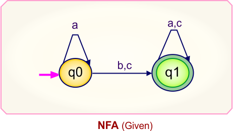
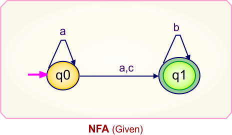
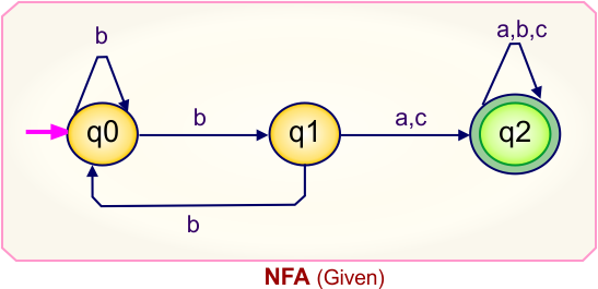
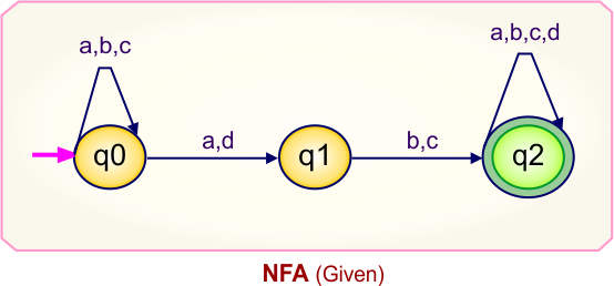
Step 01: Draw NFA Graph
The following is the NFA graph that needs to be converted to a DFA.
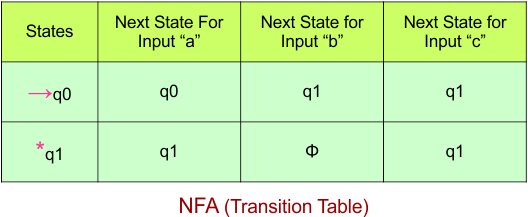
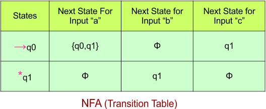
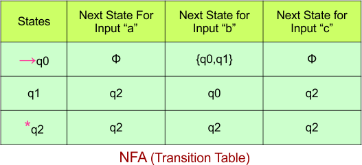
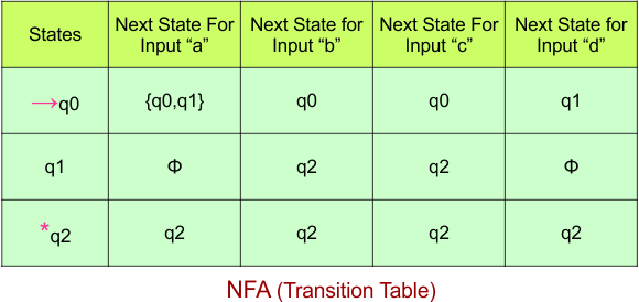
Step 02: Draw the NFA transition Table.
The NFA transition table of the above NFA is given below
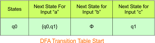
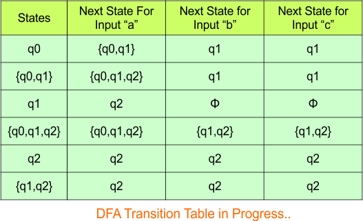
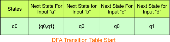
Step 03: Conversion of NFA to DFA Transition Table
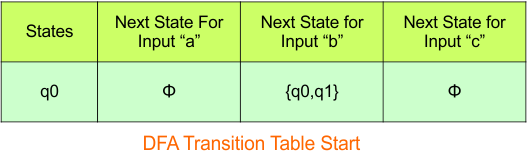
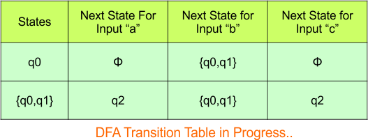
Step 3.1: Select the first two rows of the NFA transition table, which will become the first two rows of the DFA transition table.
In the above DFA Table
- State Column Contains: “q0”
- Input columns contain: “q0q1”, “q0”, “q1”
Step 3.2: State “q0q1” and “q1” are new states because it is present in the DFA’s input columns but do not exist in the state column. Put “q0q1” in the state column along with its transitions.
Transition at “q0q1” against all inputs “a”, “b”, and “c”
For input “a”
δ([q0q1], a) = δ(q0, a) ∪ δ(q1, a)
= {q0q1} ∪ {ϕ}
= {q0q1}
For input “b”
δ([q0q1], b) = δ(q0, b) ∪ δ(q1, b)
= {q0} ∪ {ϕ}
= {q0}
For input “c”
δ([q0q1], c) = δ(q0, c) ∪ δ(q1, c)
= {q1} ∪ {ϕ}
= {q1}
Hence, the updated DFA table is given below.
In the above DFA Table
- State Column Contains: “q0”, “q0q1”
- Input columns contain: “q0”, “q0q1”, “q1”
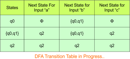
Repeat Step 3.2: “q1” is a new state because it is present in the input columns of the DFA but does not exist in the state column. Put “q1” in the state column along with its transitions.
Transition at state “q1”
For input “a”
δ([q1], a) = {ϕ}
For input “b”
δ([q1], b) = {ϕ}
For input “c”
δ([q1], c) = {ϕ}
The updated DFA Table is given below
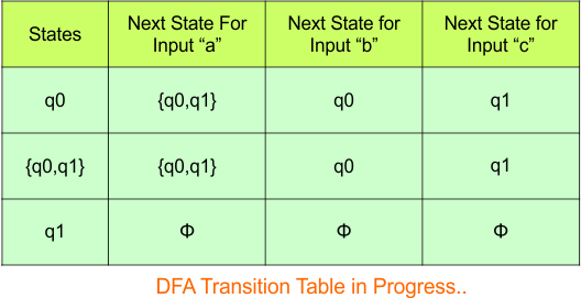
In the above DFA Table
- State Column Contains: “q0”, “q0q1”, “q1”
- Input columns contain: “q0”, “q0q1”, “q1”
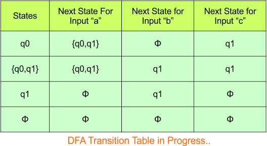
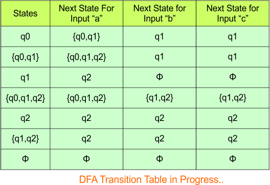
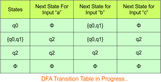
No new state exists in the DFA table, except ϕ. Transition at “ϕ” against all inputs will always stay at “ϕ”. The updated DFA Table is given below
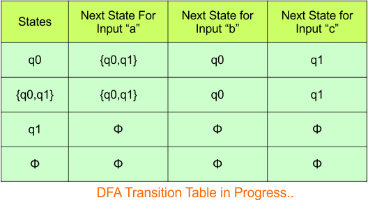
At this stage, no new state remains for the state column. The DFA table is one step away from being complete.
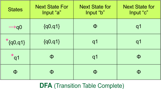
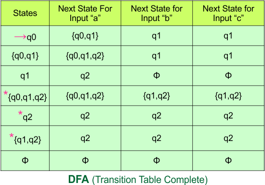
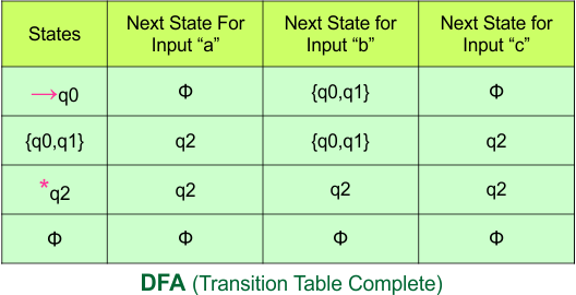
Step 3.3: At this stage, all newly generated states in the DFA table are executed successfully for their transitions, so the DFA table is ready.
Important: As “q1” was the final state in NFA Table. That’s why, all those states will be the final states where “q1” is present. Simply mark with “*” to represent the final state.
So, the following is the updated table of the DFA with its final states
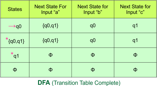
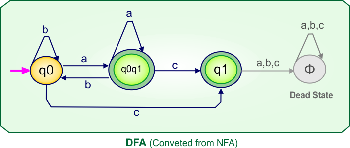
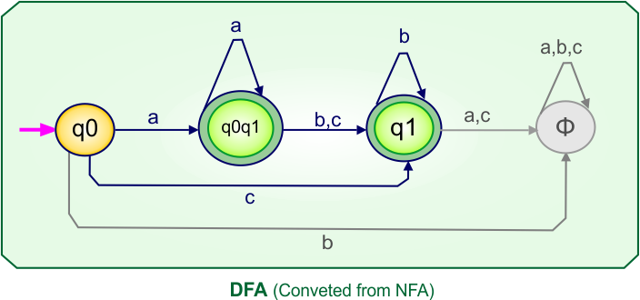
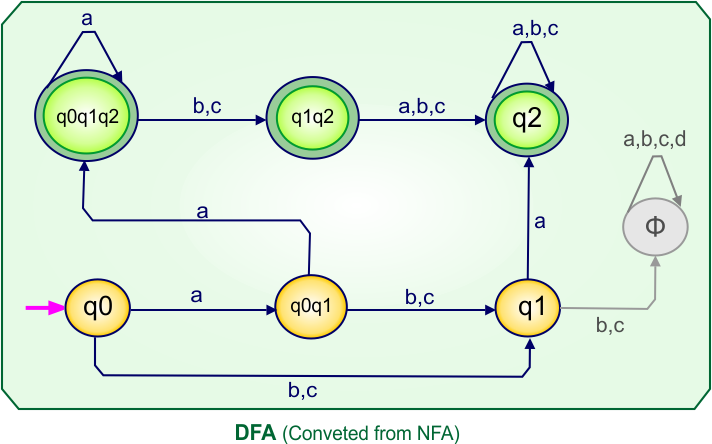
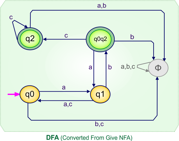
Step 4: Now draw the DFA according to the DFA Transition Table
According to the DFA transition table, we can generate the following DFA diagram.
NFA to DFA Conversion Example 2.2
Step 01: Draw NFA Graph
The following is the NFA graph that needs to be converted to a DFA.
Step 02: Draw the NFA transition Table.
The NFA transition table of the above NFA is given below
Step 03: Conversion of NFA to DFA Transition Table
Step 3.1: Select the first two rows of the NFA transition table, which will become the first two rows of the DFA transition table.
In the above DFA Table
- State Column Contains: “q0”
- Input columns contain: “q0”, “q1”
Step 3.2: State “q1” is a new state because it is present in the DFA’s input columns but does not exist in the state column. Put “q1” in the state column along with its transitions.
Transition at state “q1” against all inputs “a”, “b”, and “c”
For input “a”
δ([q1], a) = {q1}
For input “b”
δ([q1], b) = {ϕ}
For input “c”
δ([q1], c) = {q1}
Hence, the updated DFA table is given below.
In the above DFA Table
- State Column Contains: “q0”, “q1”
- Input columns contain: “q0”, “q1”
No new state exists in the DFA table, except ϕ. Transition at “ϕ” against all inputs will always stay at “ϕ”. The updated DFA Table is given below
Step 3.3: At this stage, all newly generated states in the DFA table are executed successfully for their transitions, so the DFA table is ready.
Important: As “q1” was the final state in NFA Table. That’s why, all those states will be the final states where “q1” is present. Simply mark with “*” to represent the final state.
So, the following is the updated table of the DFA with its final states
Step 4: Now draw the DFA according to the DFA Transition Table
According to the DFA transition table, we can generate the following DFA diagram.
NFA to DFA Conversion Example 2.3
Step 01: Draw NFA Graph
The following is the NFA graph that needs to be converted to a DFA.
Step 02: Draw the NFA transition Table.
The NFA transition table of the above NFA is given below
Step 03: Conversion of NFA to DFA Transition Table
Step 3.1: Select the first two rows of the NFA transition table, which will become the first two rows of the DFA transition table.
In the above DFA Table
- State Column Contains: “q0”
- Input columns contain: “q0q1”, “q1”
Step 3.2: States “q0q1” and “q1” are new states because they are present in the DFA’s input columns but do not exist in the state column. Add states “q0q1” and “q1” along with their transitions to the state column.
Transition calculations for state “q0q1”
For input “a”
δ([q0q1], a) = δ(q0, a) ∪ δ(q1, a)
= {q0q1} ∪ {ϕ}
= {q0q1}
For input “b”
δ([q0q1], b) = δ(q0, b) ∪ δ(q1, b)
= {ϕ} ∪ {q1}
= {q1}
For input “c”
δ([q0q1], c) = δ(q0, c) ∪ δ(q1, c)
= {q1} ∪ {ϕ}
= {q1}
Transition at state “q1” against all inputs “a”, “b”, and “c”
For input “a”
δ([q1], a) = {ϕ}
For input “b”
δ([q1], b) = {q1}
For input “c”
δ([q1], c) = {ϕ}
Hence, the updated DFA table is given below.
In the above DFA Table
- State Column Contains: “q0”, “q0q1”, “q1”
- Input columns contain: “q0”, “q0q1”, “q1”
Repeat Step 3.2: No new state exists in the DFA table, except ϕ. Transition at “ϕ” against all inputs will always stay at “ϕ”. The updated DFA Table is given below
Step 3.3: At this stage, all newly generated states in the DFA table are executed successfully for their transitions, so the DFA table is ready.
Important: As “q1” was the final state in NFA Table. That’s why, all those states will be the final states where “q1” is present. Simply mark with “*” to represent the final state.
So, the following is the updated table of the DFA with its final states
Step 4: Now draw the DFA according to the DFA Transition Table
According to the DFA transition table, we can generate the following DFA diagram.
NFA to DFA Category-03 Examples: 2-States, 4-Input Symbols
Category 03 covers NFA to DFA conversions for machines with two states over the four input alphabets {a,b,c,d}.
NFA to DFA Conversion Example 3.1
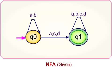
Step 01: Draw NFA Graph
The following is the NFA graph that needs to be converted to a DFA.
Step 02: Draw the NFA transition Table.
The NFA transition table of the above NFA is given below
Step 03: Conversion of NFA to DFA Transition Table
Step 3.1:Select the first two rows of the NFA transition table, which will become the first two rows of the DFA transition table.
In the above DFA Table
- State Column Contains: “q0”
- Input columns contain: “q0”, “q0q1”, “q1”
Step 3.2: State “q0q1” and “q1” are new states because it is present in the DFA’s input columns but do not exist in the state column. Put “q0q1” in the state column along with its transitions.
Transition at state “q0q1” against all inputs “a”, “b”, “c”, and “d” is given below
For input “a”
δ([q0q1], a) = δ(q0, a) ∪ δ(q1, a)
= {qq} ∪ {ϕ}
= {qq}
For input “b”
δ([q0q1], b) = δ(q0, b) ∪ δ(q1, b)
= {ϕ} ∪ {q}
= {qq}
For input “c”
δ([q0q1], c) = δ(q0, c) ∪ δ(q1, c)
= {ϕ} ∪ {ϕ}
= {ϕ}
For input “d”
δ([q0q1], d) = δ(q0, d) ∪ δ(q1, d)
= {ϕ} ∪ {ϕ}
= {ϕ}
Transition at state “q1”
For input “a”
δ([q1], a) = {ϕ}
For input “b”
δ([q1], b) = {ϕ}
For input “c”
δ([q1], c) = {ϕ}
For input “d”
δ([q1], d) = {ϕ}
The updated DFA Table is given below
In the above DFA Table
- State Column Contains: “q0”, “q0q1”, “q1”
- Input columns contain: “q0”, “q0q1”, “q1”
No new state exists in the DFA table, except ϕ. Transition at “ϕ” against all inputs will always stay at “ϕ”. The updated DFA Table is given below
At this stage, no new state remains for the state column. The DFA table is one step away from being complete.
Step 3.3: At this stage, all newly generated states in the DFA table are executed successfully for their transitions, so the DFA table is ready.
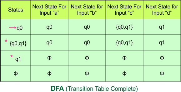
Important: As “q1” was the final state in NFA Table. That’s why, all those states will be the final states where “q1” is present. Simply mark with “*” to represent the final state.
So, the following is the updated table of the DFA with its final states
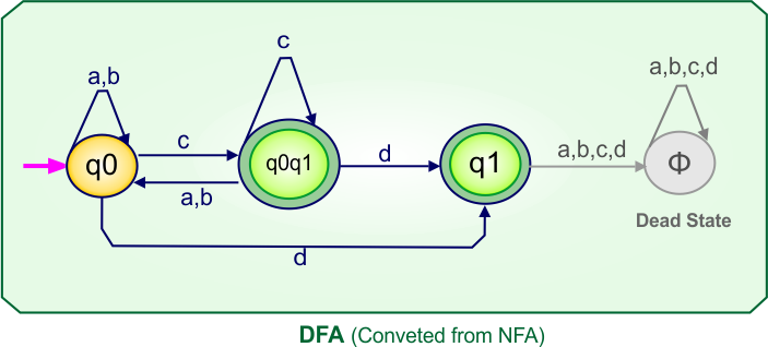
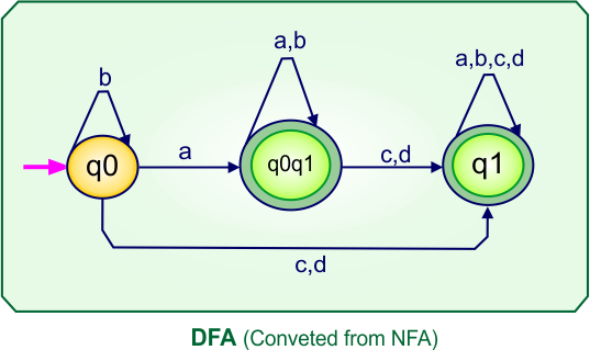
Step 4: Now draw the DFA according to the DFA Transition Table
According to the DFA transition table, we can generate the following DFA diagram.
NFA to DFA Conversion Example 3.2
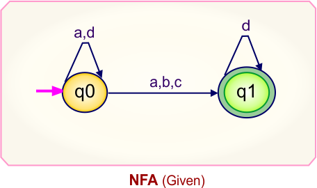
Step 01: Draw NFA Graph
The following is the NFA graph that needs to be converted to a DFA.
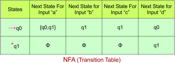
Step 02: Draw the NFA transition Table.
The NFA transition table of the above NFA is given below
Step 03: Conversion of NFA to DFA Transition Table
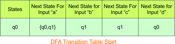
Step 3.1:Select the first two rows of the NFA transition table, which will become the first two rows of the DFA transition table.
In the above DFA Table
- State Column Contains: “q0”
- Input columns contain: “q0q1”, “q0”, “q1”
Step 3.2: State “q0q1” and “q1” are new states because they are present in the DFA’s input columns but do not exist in the state column. Put “q0q1” and “q1” in the state column along with their transitions.
Transition at state “q0q1” against all inputs “a”, “b”, “c”, and “d” is given below
For input “a”
δ([q0q1], a) = δ(q0, a) ∪ δ(q1, a)
= {q0q1} ∪ {q1}
= {q0q1}
For input “b”
δ([q0q1], b) = δ(q0, b) ∪ δ(q1, b)
= {q0} ∪ {q1}
= {q0q1}
For input “c”
δ([q0q1], c) = δ(q0, c) ∪ δ(q1, c)
= {q1} ∪ {q1}
= {q1}
For input “d”
δ([q0q1], d) = δ(q0, d) ∪ δ(q1, d)
= {q1} ∪ {q1}
= {q1}
Transition at state “q1” against all inputs “a”, “b”, “c”, and “d”
For input “a”
δ([q1], a) = {q1}
For input “b”
δ([q1], b) = {q1}
For input “c”
δ([q1], c) = {q1}
For input “D”
δ([q1], d) = {q1}
The updated DFA Table is given below
In the above DFA Table
- State Column Contains: “q0”, “q0q1″,”q1”
- Input columns contain: “q0”, “q0q1″,”q1”
No new state remains for the state column. The DFA table is one step away from being complete.
Step 3.3: All newly generated states in the DFA table are executed successfully for their transitions, so the DFA table is ready.
Important: As “q1” was the final state in NFA Table. That’s why, all those states will be the final states where “q1” is present. Simply mark with “*” to represent the final state.
So, the following is the updated table of the DFA with its final states
Step 4: Now draw the DFA according to the DFA Transition Table
According to the DFA transition table, we can generate the following DFA diagram.
NFA to DFA Conversion Example 3.3
Step 01: Draw NFA Graph
The following is the NFA graph that needs to be converted to a DFA.
Step 02: Draw the NFA transition Table.
The NFA transition table of the above NFA is given below
Step 03: Conversion of NFA to DFA Transition Table
Step 3.1:Select the first two rows of the NFA transition table, which will become the first two rows of the DFA transition table.
In the above DFA Table
- State Column Contains: “q0”
- Input columns contain: “q0q1”, “q1”, “q0”
Step 3.2: States “q0q1” and “q1” are new states because they are present in the DFA’s input columns but do not exist in the state column. Add states “q0q1” and “q1” along with their transitions to the state column.
Transition at state “q0q1” against all inputs “a”, “b”, “c”, and “d” is given below
For input “a”
δ([q0q1], a) = δ(q0, a) ∪ δ(q1, a)
= {q0q1} ∪ {ϕ}
= {q0q1}
For input “b”
δ([q0q1], b) = δ(q0, b) ∪ δ(q1, b)
= {q1} ∪ {ϕ}
= {q1}
For input “c”
δ([q0q1], c) = δ(q0, c) ∪ δ(q1, c)
= {q1} ∪ {ϕ}
= {q1}
For input “d”
δ([q0q1], d) = δ(q0, d) ∪ δ(q1, d)
= {q0} ∪ {q1}
= {q0q1}
Transition at state “q” against all inputs “a”, “b”, “c”, and “d”
For input “a”
δ([q1], a) = {ϕ}
For input “b”
δ([q1], b) = {ϕ}
For input “c”
δ([q1], c) = {ϕ}
For input “d”
δ([q1], d) = {q1}
The updated DFA Table is given below
In the above DFA Table
- State Column Contains: “q0”, “q0q1”, “q1”
- Input columns contain: “q0”, “q0q1”, “q1”
Repeat Step 3.2: No new states exist in the DFA table, except ϕ. The transition at “ϕ” for all inputs will always remain at “ϕ”. The updated DFA table is given below.
Step 3.3: At this stage, all newly generated states in the DFA table are executed successfully for their transitions, so the DFA table is ready.
Important: As “q1” was the final state in NFA Table. That’s why, all those states will be the final states where “q1” is present. Simply mark with “*” to represent the final state.
So, the following is the updated table of the DFA with its final states
Step 4: Now draw the DFA according to the DFA Transition Table
According to the DFA transition table, we can generate the following DFA diagram.
NFA to DFA Category-04 Examples: 3-States, 2-Input Symbols
Category 04 covers NFA to DFA conversions for machines with three states over the two input alphabets {a,b} or {0,1}.
NFA to DFA Conversion Example 4.1
Problem: Draw an NFA of all binary strings in which the 2nd last bit is 1 and convert this NFA to its corresponding DFA.
Step 01: Draw NFA Graph.
The following is the NFA graph that has to be converted into a DFA.
Step 02: Draw the NFA transition Table.
The NFA transition table of the above NFA is given below

Step 03: Conversion of NFA to DFA Transition Table
Let’s start the conversion of the NFA transition table to the DFA transition Table.
Step 3.1: Select the first two rows of the NFA transition table, which will become the first two rows of the DFA transition table given below.
In the above DFA Table
- State Column Contains: “q0”
- Input columns contain: “q0”, “q0q1”
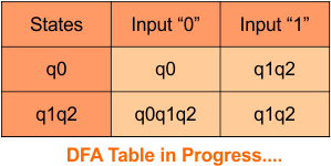
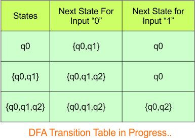
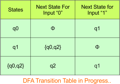
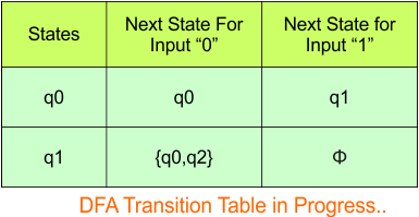
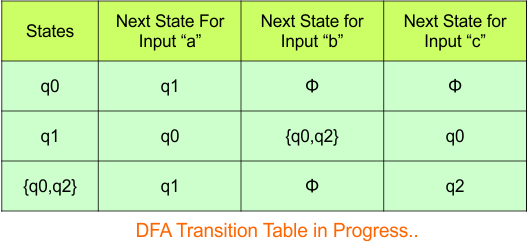
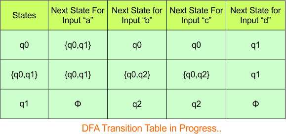
Step 3.2: State “q0q1” is a new state because it is present in the input columns of the DFA but does not exist in the state column. Put “q0q1” in the state column along with its transitions.
Transition calculations for state “q0q1”
For input “0”
δ([q0q1], 0) = δ(q0, 0) ∪ δ(q1, 0)
= {q0} ∪ {q2}
= [q0q2]
For input “1”
δ([q0q1], 1) = δ(q0, 1) ∪ δ(q1, 1)
= {q0q1} ∪ {q2}
= {q0q1q2}
The transition of state “q0q1” against input “0” is “q0q2”, and the transition against input “1” is “q0q1q2”. Hence, the updated DFA table is given below.

In the above DFA Table
- State Column Contains: “q0”, “q0q1”
- Input columns contain: “q0”, “q0q1”, “q0q2”, “q0q1q2”
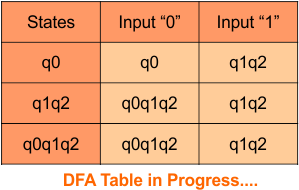
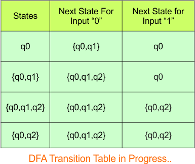
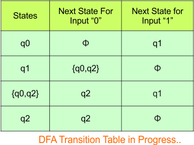
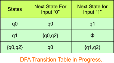
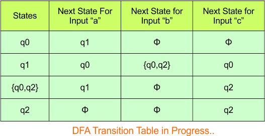
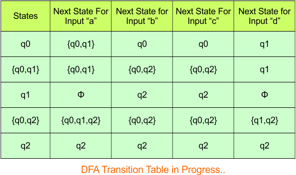
Repeat Step 3.2: “q0q2” and “q0q1q2” are new states because it is present in the input columns of the DFA but do not exist in the state column. Put “q0q2” and “q0q1q2” in the state column along with their transitions.
Transition calculations for state “q0q2”
For input “0”
δ([q0q2], 0) = δ(q0, 0) ∪ δ(q2, 0)
= {q0}
= [q0]
For input “1”
δ([q0q2], 1) = δ(q0, 1) ∪ δ(q2, 1)
= {q0q1}
= {q0q1}
= [q0q1]
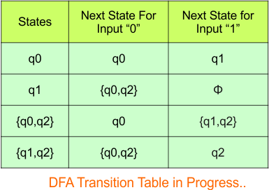
Transition calculations for state “q0q1q2”
For input “0”
δ([q0q1q2], 0) = δ(q0, 0) ∪ δ(q1, 0) ∪ δ(q2, 0)
= {q0} ∪ {ϕ} ∪ {q2}
= [q0q2]
For input “1”
δ([q0q1q2], 1) = δ(q0, 1) ∪ δ(q1, 1) ∪ δ(q2, 1)
= {q0} ∪ {q1} ∪ {q2}
= [q0q1q2]
Hence, the updated DFA table is given below, where
- The Transition of “q0q1q2” against input “0” is “q0q2”, and the transition against input “1” is “q0q1q2”.
- The Transition of “q0q2” against input “0” is “q0”, and the transition against input “1” is “q0q1”.
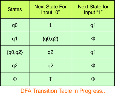
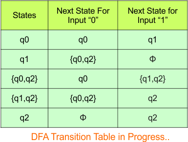
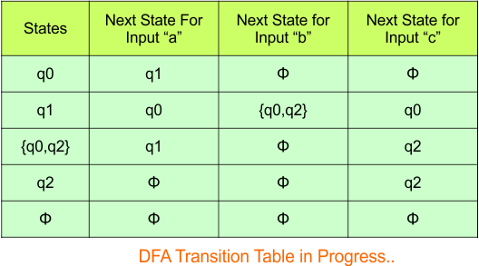
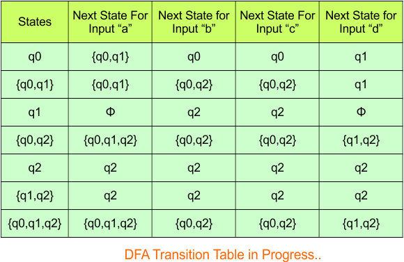
In the above DFA Table
- State Column Contains: “q0”, “q0q1”, “q0q2”, “q0q1q2”
- Input columns contain: “q0”, “q0q1”, “q0q2”, “q0q1q2”
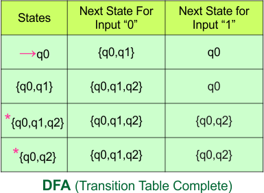
At this stage, no new state remains. The DFA table is one step away to complete.
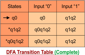
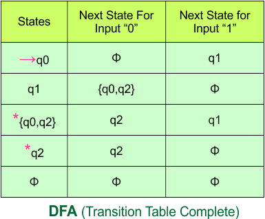
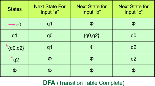
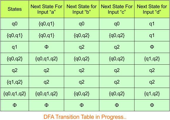
Step 3.3: State “q2” was the final state in the NFA Table. That’s why all those states will be the final states where “q2” is present in the DFA state column. Simply mark with “*” to represent the final state.
Here is the complete DFA transition table with its final states
![]()
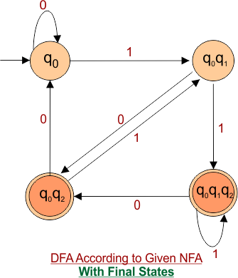
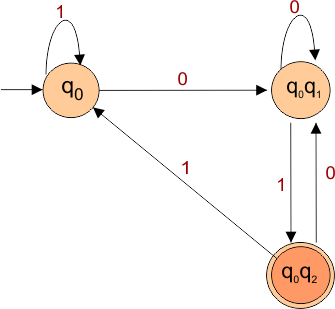
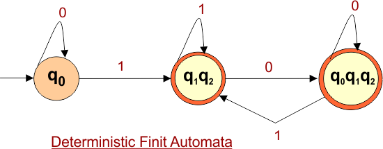
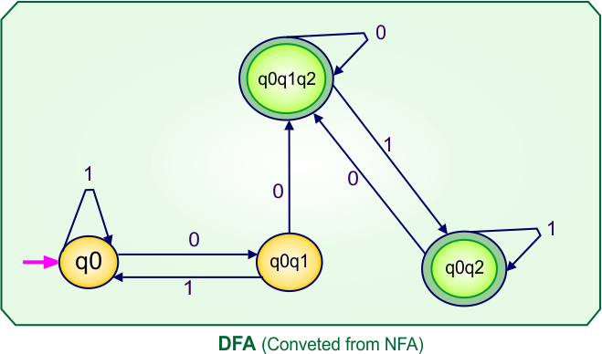
Step 4: Now draw the DFA according to the DFA transition table
The DFA transition table contains four states (q0, q0q1, q0q2, q0q1q2) in its state column. Thus, the desired DFA machine graph will contain these states, and transitions will be made according to the DFA transition table.
NFA to DFA Conversion Example 4.2
Step 01: Draw NFA Graph
The following is the NFA graph that needs to be converted to a DFA.
Step 02: Draw the NFA transition Table.
The following is the NFA transition table which is derived from the given NFA.
Step 03: Conversion of NFA to DFA Transition Table
Step 3.1: Select the first two rows of the NFA transition table, which will become the first two rows of the DFA transition table, given below

In the above DFA Table
- State Column Contains: “q0”
- Input columns contain: “q0q1”, “q0”
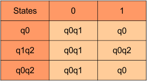
Step 3.2: State “q0q1” is a new state because it is present in the input columns of the DFA but does not exist in the state column. Put “q0q1” in the state column along with its transitions.
Transition calculations for state “q0q1”
For input “0”
δ([q0q1], 0) = δ(q0, 0) ∪ δ(q1, 0)
= {q0q1} ∪ {ϕ}
= {q0q1}
For input “1”
δ([q0q1], 1) = δ(q0, 1) ∪ δ(q1, 1)
= {q0} ∪ {q2}
= {q0q2}
The transition of state “q0q1” against input “0” is “q0q1“, and the transition against input “1” is “q0q2“. Hence, the updated DFA table is given below.
In the above DFA Table
- State Column Contains: “q0”, “q0q1”
- Input columns contain: “q0”, “q0q1”, “q0q2”
Repeat Step 3.2: “q0q2” is a new state because it is present in the input columns of the DFA but does not exist in the state column. Put “q0q2” in the state column along with their transitions.
Transition calculations for state “q0q2”
For input “0”
δ([q0q2], 0) = δ(q0, 0) ∪ δ(q2, 0)
= {q0q1} ∪ {ϕ}
= {q0q1}
For input “1”
δ([q0q2], 1) = δ(q0, 1) ∪ δ(q2, 1)
= {q0} ∪ {ϕ}
= {q0}
Hence, the updated DFA table is given below, where
- The Transition of “q0q2” against input “0” is “q0q1”, and the transition against input “1” is “q0”.
In the above DFA Table
- State Column Contains: “q0”, “q1q2”, “q0q2”
- Input columns contain: “q0”, “q1q2”, “q0q2”
At this stage, no new state remains. The DFA table is one step away to complete.
Step 3.3: State “q2” was the final state in the NFA Table. That’s why all those states will be the final states where “q2” is present in the DFA state column. Simply mark with “*” to represent the final state.
So, the following is the updated table of DFA with its final states

Step 4: Draw DFA
Create a DFA based on the provided DFA transition table. The transition table includes three states: q0, q0q1, and q0q2.
NFA to DFA Conversion Example 4.3
Step 01: Draw NFA Graph
The following is the NFA graph for conversion into DFA.
Step 02: Draw the NFA Transition Table.
The NFA transition table of the above NFA is given below

Note: All transitions are made according to the NFA transition table to get the DFA transition table.
Step 03: Conversion of NFA To DFA transition Table
Initially, the NFA table has three states: q0 and q1 Any new state is added to the DFA states column.
First, Select the first two rows of the NFA transition table, which will become the first two rows of the DFA transition table. It is given below
The q0q1 is a new state (as it not exist in NFA table) and will be added to the states column of DFA table. Following is the Transitions for q0q1.
δ([q0q1], 0) = δ(q0, 0) ∪ δ(q1, 0)
= {q0q1} ∪ {ϕ}
= {q0q1}
δ([q0q1], 1) = δ(q0, 1) ∪ δ(q1, 1)
= {ϕ} ∪ {q1q2}
= {q1q2}
Following is the updated DFA table
The q1q2 is a new state and will be added to the states column. Following is the Transitions for q1q2.
δ([q1q2], 0) = δ(q1, 0) ∪ δ(q2, 0)
= {ϕ} ∪ {q0}
= {q0}
δ([q1q2], 1) = δ(q1, 1) ∪ δ(q2, 1)
= {q1q2} ∪ {ϕ}
= {q1q2}
So, the following is the updated table of DFA with its final states

At this stage, all newly generated states are executed successfully for their transitions. So, the DFA table is ready.
Important: As q0 was the final state in NFA Table. That’s why, all those states will be the final states where q0 is present. Simply mark with “*” to represent the final state.
Step 4: Now draw DFA according to the DFA transition table
The DFA machine graph will include similar states and transitions based on the DFA transition table.

NFA to DFA Conversion Example 4.4
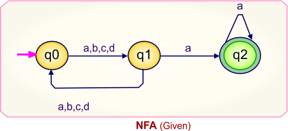
Step 01: Draw NFA Graph
The following is the NFA graph that needs to be converted to a DFA.

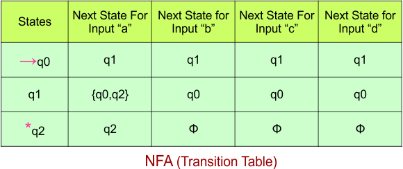
Step 02: Draw the NFA Transition Table.
The following is the NFA transition table, which is derived from the given NFA.
Step 03: Conversion of NFA to DFA Transition Table
Let’s start the conversion of the NFA transition table to the DFA transition Table.
Step 3.1: Select the first two rows of the NFA transition table, which will become the first two rows of the DFA transition table given below.

In the above DFA Table
- State Column Contains: “q0”
- Input columns contain: “q0q1”, “q2”
Step 3.2: State “q0q1” and “q2” are new states because it is present in the input columns of the DFA but do not exist in the state column. Put “q0q1” and “q2” in the state column along with its transitions.
Transition calculations for state “q0q1”
For input “0”
δ([q0q1], 0) = δ(q0, 0) ∪ δ(q1, 0)
= {q0q1} ∪ {q0}
= {q0q1}
For input “1”
δ([q0q1], 1) = δ(q0, 1) ∪ δ(q1, 1)
= {q2} ∪ {q1}
= {q1q2}
Transition calculations for state “q2”
For input “0”
δ([q2], 0) = {qϕ}
For input “1”
δ([q2], 1) = {q0q1}
Hence, the updated DFA table is given below, where
- The Transition of “q0q1” against input “0” is “q0q1“, and the transition against input “1” is “q1q2“.
- The Transition of “q2” against input “0” is “qϕ“, and the transition against input “1” is “q0q1“.
In the above DFA Table
- State Column Contains: “q0”, “q0q1”, “q2”
- Input columns contain: “q0q1”, “q2”, “q1q2”, “qϕ“
Repeat Step 3.2: “q1q2” and “qϕ” are new states because it is present in the input columns of the DFA but do not exist in the state column. Put “q1q2” and “qϕ” in the state column along with their transitions.
Transition calculations for state “q1q2”
For input “0”
δ([q1q2], 0) = δ(q1, 0) ∪ δ(q2, 0)
= {q0} ∪ {ϕ}
= {q0}
For input “1”
δ([q1q2], 1) = δ(q1, 1) ∪ δ(q2, 1)
= {q1} ∪ {q0q1}
= {q0q1}
Transition calculations for state “qϕ”
For input “0”
δ([qϕ], 0) = {qϕ}
For input “1”
δ([qϕ], 1) = {qϕ}
Hence, the updated DFA table is given below, where
- The Transition of “q0q2” against input “0” is “q0“, and the transition against input “1” is “q0q1“.
- The Transition of “qϕ” against input “0” is “qϕ“, and the transition against input “1” is “qϕ“.
In the above DFA Table
- State Column Contains: “q0”, “q0q1”, “q2”, “q1q2”, “qϕ“
- Input columns contain: “q0”, “q0q1”, “q2”, “q1q2”, “qϕ“
At this stage, no new state remains. The DFA table is one step away to complete.
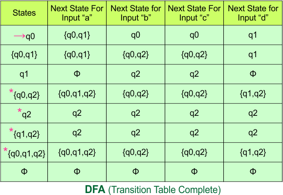
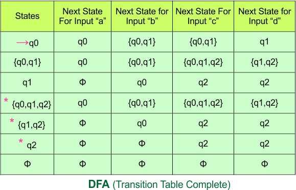
Step 3.3: State “q2” was the final state in the NFA Table. That’s why all those states will be the final states where “q2” is present in the DFA state column. Simply mark with “*” to represent the final state.
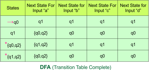
Here is the complete DFA transition table with its final states
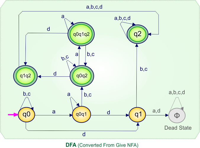
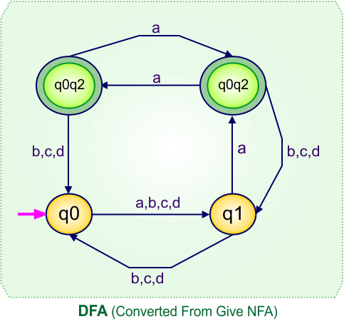
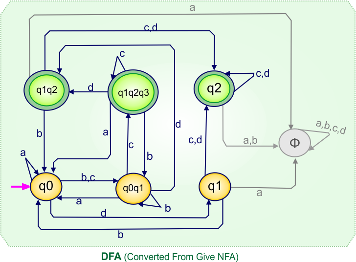
Step 4: Now draw DFA according to the DFA transition table
The following is the DFA machine that derives from DFA transition Table.

NFA to DFA Conversion Example 4.5
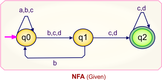
Step 01: Draw NFA Graph
The following is the NFA graph that needs to be converted to a DFA.
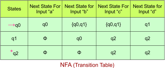
Step 02: Draw the NFA Transition Table.
The NFA transition table of the above NFA is given below
Step 03: Conversion of NFA to DFA Transition Table
Step 3.1:Select the first two rows of the NFA transition table, which will become the first two rows of the DFA transition table.
Step 3.2: Only “q0” exists in the state column of the DFA. However, the state “q1” occurs in the DFA table, which does not appear in the state column. Therefore, we should simply add this state to the state column. The transitions for “q1” are given below
Transition at state “q1”
For input “0”
δ([q1], 0) = {q1q2}
For input “1”
δ([q1], 1) = {q1}
The Update DFA Table is given below
Repeat Step 3.2: State “q0” and “q1” exist in the state column of the DFA. However, the state “q1q2” occurs in the DFA table but does not appear in the state column. Therefore, we should simply add this state to the state column.
Transition at state “q1q2”
For input “0”
δ([q1q2], 0) = δ(q1, 0) ∪ δ(q2, 0)
= {q1q2} ∪ {q2}
= {q1q2}
For input “1”
δ([q1q2], 1) = δ(q1, 1) ∪ δ(q2, 1)
= {q1} ∪ {q1q2}
= {q1q2}
The Update DFA Table is given below
Step 3.3: At this stage, all newly generated states in the DFA table are executed successfully for their transitions, so the DFA table is ready.
Important: As q2 was the final state in NFA Table. That’s why, all those states will be the final states where q2 is present. Simply mark with “*” to represent the final state.
So, the following is the updated table of the DFA with its final states
Step 4: Now draw the DFA according to the DFA Transition Table
According to the DFA transition table, we can generate the following DFA diagram.
NFA to DFA Conversion Example 4.6
Step 01: Draw NFA Graph
The following is the NFA graph that needs to be converted to a DFA.
Step 02: Draw the NFA Transition Table.
The NFA transition table of the above NFA is given below
Step 03: Conversion of NFA to DFA Transition Table
Step 3.1:Select the first two rows of the NFA transition table, which will become the first two rows of the DFA transition table.
Step 3.2: Only “q0” exists in the state column of the DFA. However, the state “q0q1” occurs in the DFA table but does not appear in the state column. Therefore, we should simply add this state to the state column. The transitions for “q0q1” are given below
Transition at state “q0q1”
For input “0”
δ([q0q1], 0) = δ(q0, 0) ∪ δ(q1, 0)
= {q0q1} ∪ {ϕ}
= {q0q1}
For input “1”
δ([q0q1], 1) = δ(q0, 1) ∪ δ(q1, 1)
= {q0} ∪ {q2}
= {q0q2}
The Update DFA Table is given below
Repeat Step 3.2: State “q0” and “q0q1” exist in the state column of the DFA. However, the state “q0q2” occurs in the DFA table but does not appear in the state column. Therefore, we should simply add these states to the state column.
Transition at state “q0q2“
For input “0”
δ([q0q2], 0) = δ(q0, 0) ∪ δ(q2, 0)
= {q0q1} ∪ {ϕ}
= {q0q1}
For input “1”
δ([q0q2], 1) = δ(q0, 1) ∪ δ(q2, 1)
= {q0} ∪ {ϕ}
= {q0}
The Update DFA Table is given below
Step 3.3: At this stage, all newly generated states in the DFA table are executed successfully for their transitions, so the DFA table is ready.
Important: As q2 was the final state in NFA Table. That’s why, all those states will be the final states where q2 is present. Simply mark with “*” to represent the final state.
So, the following is the updated table of the DFA with its final states
Step 4: Now draw the DFA according to the DFA Transition Table
According to the DFA transition table, we can generate the following DFA diagram.
NFA to DFA Conversion Example 4.7
Step 01: Draw NFA Graph
The following is the NFA graph that needs to be converted to a DFA.
Step 02: Draw the NFA Transition Table.
The NFA transition table of the above NFA is given below
Step 03: Conversion of NFA to DFA Transition Table
Step 3.1:Select the first two rows of the NFA transition table, which will become the first two rows of the DFA transition table.
Step 3.2: Only “q0” exists in the state column of the DFA. However, the state “q1q2” occurs in the DFA table but does not appear in the state column. Therefore, we should simply add this state to the state column. The transitions for “q1q2” are given below
Transition at state “q1q2” against both inputs “0” and “1”
For input “0”
δ([q1q2], 0) = δ(q1, 0) ∪ δ(q2, 0)
= {q1q2} ∪ {q0q1}
= {q0q1q2}
For input “1”
δ([q1q2], 1) = δ(q1, 1) ∪ δ(q2, 1)
= {q2} ∪ {q1}
= {q1q2}
The Update DFA Table is given below
Repeat Step 3.2: State “q0” and “q1q2” exist in the state column of the DFA. However, the state “q0q1q2” occurs in the DFA table but does not appear in the state column. Therefore, we should simply add these states to the state column.
Transition at state “q0q1q2” is given below
For input “0”
δ([q0q1q2], 0) = δ(q0, 0) ∪ δ(q1, 0) ∪ δ(q2, 0)
= {q0} ∪ {q1q2}∪ {q0q1}
= {q0q1q2}
For input “1”
δ([q0q1q2], 1) = δ(q0, 1) ∪ δ(q1, 1) ∪ δ(q2, 1)
= {q1q2} ∪ {q2}∪ {q1}
= {q1q2}
The Update DFA Table is given below
Step 3.3: At this stage, all newly generated states in the DFA table are executed successfully for their transitions, so the DFA table is ready.
Important: As q2 was the final state in NFA Table. That’s why, all those states will be the final states where q2 is present. Simply mark with “*” to represent the final state.
So, the following is the updated table of the DFA with its final states
Step 4: Now draw the DFA according to the DFA Transition Table
According to the DFA transition table, we can generate the following DFA diagram.
NFA to DFA Conversion Example 4.8
Step 01: Draw NFA Graph
The graph below represents an NFA that needs conversion into a DFA.
Step 02: Draw the NFA Transition Table.
The table below presents the transition table of the NFA derived from the given NFA.
Step 03: Conversion of NFA to DFA Transition Table
Let’s begin converting the NFA transition table to the DFA transition table.
Step 3.1: Select the first two rows of the NFA transition table to form the initial two rows of the DFA transition table below.
In the above DFA Table
- State Column Contains: “q0”
- Input columns contain: “q0q1”, “q0”
Step 3.2: State “q0q1” is a new state because it appears in the input columns of the DFA but does not exist in the state column. Add “q0q1” to the state column along with its transitions.
Transition calculations at state “q0q1”
For input “0”
δ([q0q1], 0) = δ(q0, 0) ∪ δ(q1, 0)
= {q0q1} ∪ {q2}
= {q0q1q2}
For input “1”
δ([q0q1], 1) = δ(q0, 1) ∪ δ(q1, 1)
= {q0} ∪ {ϕ}
= {q0}
The updated DFA table is given below.
In the above DFA Table
- State Column Contains: “q0”, “q0q1”
- Input columns contain: “q0”, “q0q1”, “q0q1q2”
Repeat Step 3.2: “q0q1q2” is a new state because it is present in the input columns of the DFA but does not exist in the state column. Put “q” in the state column along with their transitions.
Transition at state “q0q1q2”
For input “0”
δ([q0q1q2], 0) = δ(q0, 0) ∪ δ(q1, 0) ∪ δ(q2, 0)
= {q0q1} ∪ {q2} ∪ {q2}
= {q0q1q2}
For input “1”
δ([q0q1q2], 1) = δ(q0, 1) ∪ δ(q1, 1) ∪ δ(q2, 1)
= {q0} ∪ {ϕ} ∪ {q2}
= {q0q2}
The updated DFA table is given below.
In the above DFA Table
- State Column Contains: “q0”, “q0q1”, “q0q1q2”, “q0q2”
- Input columns contain: “q0”, “q0q1”, “q0q1q2”, “q0q2”
Repeat Step 3.2: “q0q2” is a new state because it is present in the input columns of the DFA but does not exist in the state column. Put “q0q2” in the state column along with their transitions.
Transition at state “q0q2”
For input “0”
δ([q0q2], 0) = δ(q0, 0) ∪ δ(q2, 0)
= {q0q1} ∪ {q2}
= {q0q1q2}
For input “1”
δ([q0q2], 1) = δ(q0, 1) ∪ δ(q2, 1)
= {q0} ∪ {q2}
= {q0q2}
The updated DFA table is given below.
In the above DFA Table
- State Column Contains: “q0”, “q0q1”, “q0q1q2″,”q0q2”
- Input columns contain: “q0”, “q0q1”, “q0q1q2″,”q0q2”
At this stage, no new states remain for the state column. The DFA table is just one step away from completion.
Step 3.3: State “q2” was the final state in the NFA table. Therefore, all states will be final states where “q2” appears in the DFA state column. Simply mark these states with “*” to indicate they are final states.
Here is the updated DFA table, which includes all its final states.
Step 4: Now draw the DFA according to the DFA transition table
The following is the converted Deterministic Finite Automaton (DFA) derived from the given Nondeterministic Finite Automaton (NFA).
NFA to DFA Conversion Example 4.9
Step 01: Draw NFA Graph
The graph below represents an NFA that needs conversion into a DFA.
Step 02: Draw the NFA Transition Table.
The table below presents the transition table of the NFA derived from the given NFA.
Step 03: Conversion of NFA to DFA Transition Table
Let’s begin converting the NFA transition table to the DFA transition table.
Step 3.1: Select the first two rows of the NFA transition table to form the initial two rows of the DFA transition table below.
In the above DFA Table
- State Column Contains: “q0”
- Input columns contain: “q0”, “q1”
Step 3.2: State “q1” is a new state because it appears in the input columns of the DFA but does not exist in the state column. Add “q1” to the state column along with its transitions.
Transition calculations at state “q1”
For input “0”
δ([q1], 0) = {q0q2}
For input “1”
δ([q1], 1) = {ϕ}
The updated DFA table is given below.
In the above DFA Table
- State Column Contains: “q0”, “q1”
- Input columns contain: “q0”, “q1”, “q0q2”
Repeat Step 3.2: “q0q2” is a new state because it is present in the input columns of the DFA but does not exist in the state column. Put “q1q2” in the state column along with their transitions.
Transition calculations at state “q0q2”
For input “0”
δ([q0q2], 0) = δ(q0, 0) ∪ δ(q2, 0)
= {ϕ} ∪ {q2}
= {q2}
For input “1”
δ([q0q2], 1) = δ(q0, 1) ∪ δ(q2, 1)
= {q1} ∪ {ϕ}
= {q1}
The updated DFA table is given below.
In the above DFA Table
- State Column Contains: “q0”, “q1”, “q0q2”
- Input columns contain: “q0”, “q1”, “q0q2”, “q2”
Repeat Step 3.2: “q2” is a new state because it is present in the input columns of the DFA but does not exist in the state column. Put “q2” in the state column along with their transitions.
Transition calculations at state “q2”
For input “0”
δ([q2], 0) = {q2}
For input “1”
δ([q2], 1) = {ϕ}
The updated DFA table is given below.
In the above DFA Table
- State Column Contains: “q0”, “q1”, “q0q2”, “q2”
- Input columns contain: “q0”, “q1”, “q0q2”, “q2”
Repeat Step 3.2: No new states exist in the DFA table, except ϕ. The transition at “ϕ” for all inputs will always remain at “ϕ”. The updated DFA table is given below.
At this stage, no new states remain for the state column. The DFA table is just one step away from completion.
Step 3.3: State “q2” was the final state in the NFA table. Therefore, all states will be final states where “q2” appears in the DFA state column. Simply mark these states with “*” to indicate they are final states.
Here is the updated DFA table, which includes all of its final states.
Step 4: Now draw the DFA according to the DFA transition table
The following is the converted Deterministic Finite Automaton (DFA) derived from the given Nondeterministic Finite Automaton (NFA).
NFA to DFA Conversion Example 4.10
Step 01: Draw NFA Graph
The graph below represents an NFA that needs conversion into a DFA.
Step 02: Draw the NFA Transition Table.
The table below presents the transition table of the NFA derived from the given NFA.
Step 03: Conversion of NFA to DFA Transition Table
Let’s begin converting the NFA transition table to the DFA transition table.
Step 3.1: Select the first two rows of the NFA transition table to form the initial two rows of the DFA transition table below.
In the above DFA Table
- State Column Contains: “q0”
- Input columns contain: “q0”, “q1”
Step 3.2: State “q1” is a new state because it appears in the input columns of the DFA but does not exist in the state column. Add “q1” to the state column along with its transitions.
Transition calculations at state “q1”
For input “0”
δ(q1, 0) = {q0q2}
For input “1”
δ(q1, 1) = {ϕ}
The updated DFA table is given below.
In the above DFA Table
- State Column Contains: “q0”, “q1”
- Input columns contain: “q0”, “q1”, “q0q2”
Repeat Step 3.2: “q0q2” is a new state because it is present in the input columns of the DFA but does not exist in the state column. Put “q0q2” in the state column along with their transitions.
Transition calculations at state “q0q2”
For input “0”
δ([q0q2], 0) = δ(q0, 0) ∪ δ(q2, 0)
= {q0} ∪ {ϕ}
= {q0}
For input “1”
δ([q0q2], 0) = δ(q0, 0) ∪ δ(q2, 0)
= {q1} ∪ {q2}
= {q1q2}
The updated DFA table is given below.
In the above DFA Table
- State Column Contains: “q0”, “q1”, “q0q2”
- Input columns contain: “q0”, “q1”, “q0q2”, “q1q2”
Repeat Step 3.2: “q1q2” is a new state because it is present in the input columns of the DFA but does not exist in the state column. Put “q1q2” in the state column along with their transitions.
Transition calculations at state “q1q2”
For input “0”
δ([q1q2], 0) = δ(q1, 0) ∪ δ(q2, 0)
= {q0q2} ∪ {ϕ}
= {q0q2}
For input “1”
δ([q1q2], 0) = δ(q1, 0) ∪ δ(q2, 0)
= {ϕ} ∪ {q2}
= {q2}
The updated DFA table is given below.
In the above DFA Table
- State Column Contains: “q0”, “q1”, “q0q2”, “q1q2”
- Input columns contain: “q0”, “q1”, “q0q2”, “q1q2”, “q2”
Repeat Step 3.2: “q2” is a new state because it is present in the input columns of the DFA but does not exist in the state column. Put “q2” in the state column along with its transitions.
Transition calculations at state “q2”
For input “0”
δ([q2], 0) = {ϕ}
For input “1”
δ([q2], 0) = {q2}
The updated DFA table is given below.
In the above DFA Table
- State Column Contains: “q0”, “q1”, “q0q2”, “q1q2”, “q2”
- Input columns contain: “q0”, “q1”, “q0q2”, “q1q2”, “q2”
Repeat Step 3.2: No new states exist in the DFA table, except ϕ. The transition at “ϕ” for all inputs will always remain at “ϕ”. The updated DFA table is given below.
At this stage, no new states remain for the state column. The DFA table is just one step away from completion.
Step 3.3: State “q2” was the final state in the NFA table. Therefore, all states will be final states where “q2” appears in the DFA state column. Simply mark these states with “*” to indicate they are final states.
Here is the updated DFA table, which includes all of its final states.
Step 4: Now draw the DFA according to the DFA transition table
The following is the converted Deterministic Finite Automaton (DFA) derived from the given Nondeterministic Finite Automaton (NFA).
NFA to DFA Category-05 Examples: 3-States, 3-Input Symbols
Category 05 covers NFA to DFA conversions for machines with three states over the three input alphabets {a,b,c}.
NFA to DFA Conversion Example 5.1
Step 01: Draw NFA Graph
The following is the NFA graph that needs to be converted to a DFA.
Step 02: Draw the NFA Transition Table.
The NFA transition table of the above NFA is given below
Step 03: Conversion of NFA to DFA Transition Table
Step 3.1: Select the first two rows of the NFA transition table, which will become the first two rows of the DFA transition table.
In the above DFA Table
- State Column Contains: “q0”
- Input columns contain: “q0″,”q0q1″,”q1”
Step 3.2: States “q0q1” and “q1” are new states because they are present in the DFA’s input columns but do not exist in the state column. Add states “q0q1” and “q1” along with their transitions to the state column.
Transition calculations at state “q0q1”
For input “a”
δ([q0q1], a) = δ(q0, a) ∪ δ(q1, a)
= {q0q1} ∪ {q2}
= {q0q1q2}
For input “b”
δ([q0q1], b) = δ(q0, b) ∪ δ(q1, b)
= {q1} ∪ {ϕ}
= {q1}
For input “c”
δ([q0q1], c) = δ(q0, c) ∪ δ(q1, c)
= {q1} ∪ {ϕ}
= {q1}
Transition at state “q1“
For input “a”
δ([q1], a) = {q2}
For input “b”
δ([q1], b) = {ϕ}
For input “c”
δ([q1], c) = {ϕ}
The updated DFA table is given below.
In the above DFA Table
- State Column Contains: “q0”, “q0q1”, “q1”
- Input columns contain: “q0”, “q0q1”, “q1”, “q0q1q2”, “q2”
Repeat Step 3.2: States “q0q1q2” and “q2” are new states because they are present in the DFA’s input columns but do not exist in the state column. Add states “q0q1q2” and “q2” along with their transitions to the state column.
Transition at state “q0q1q2”
For input “a”
δ([q0q1q2], a) = δ(q0, a) ∪ δ(q1, a) ∪ δ(q2, a)
= {q0q1} ∪ {q2} ∪ {q2}
= {q0q1q2}
For input “b”
δ([q0q1q2], b) = δ(q0, b) ∪ δ(q1, b) ∪ δ(q2, b)
= {q1} ∪ {ϕ} ∪ {q2}
= {q1q2}
For input “c”
δ([q0q1q2], c) = δ(q0, c) ∪ δ(q1, c) ∪ δ(q2, c)
= {q1} ∪ {ϕ} ∪ {q2}
= {q1q2}
Transition at state “q2“
For input “a”
δ([q2], a) = {q2}
For input “b”
δ([q2], b) = {q2}
For input “c”
δ([q2], c) = {q2}
The updated DFA Table is given below
In the above DFA Table
- State Column Contains: “q0”, “q0q1”, “q1”, “q0q1q2”, “q2”
- Input columns contain: “q0”, “q0q1”, “q1”, “q0q1q2”, “q2”, “q1q2”
Repeat Step 3.2: “q1q2” is a new state because it is present in the input columns of the DFA but does not exist in the state column. Put “q1q2” in the state column along with their transitions.
Transition at state “q1q2”
For input “a”
δ([q1q2], a) = δ(q1, a) ∪ δ(q2, a)
= {q2} ∪ {q2}
= {q2}
For input “b”
δ([q1q2], b) = δ(q1, b) ∪ δ(q2, b)
= {ϕ} ∪ {q2}
= {q2}
For input “c”
δ([q1q2], c) = δ(q1, c) ∪ δ(q2, c)
= {ϕ} ∪ {q2}
= {q2}
Hence, the updated DFA table is given below.
Repeat Step 3.2: No new state exists in the DFA table, except ϕ. Transition at “ϕ” against all inputs will always stay at “ϕ”. The updated DFA Table is given below
At this stage, no new state remains for the state column. The DFA table is one step away from being complete.
Step 3.3: At this stage, all newly generated states in the DFA table are executed successfully for their transitions, so the DFA table is ready.
Important: As “q2” was the final state in NFA Table. That’s why, all those states will be the final states where “q2” is present. Simply mark with “*” to represent the final state.
So, the following is the updated table of the DFA with its final states
Step 4: Now draw the DFA according to the DFA Transition Table
According to the DFA transition table, we can generate the following DFA diagram.
NFA to DFA Conversion Example 5.2
Step 01: Draw NFA Graph
The following is the NFA graph that needs to be converted to a DFA.
Step 02: Draw the NFA Transition Table.
The NFA transition table of the above NFA is given below
Step 03: Conversion of NFA to DFA Transition Table
Step 3.1: Select the first two rows of the NFA transition table, which will become the first two rows of the DFA transition table.
In the above DFA Table
- State Column Contains: “q0”
- Input columns contain: “q0”, “q1”
Step 3.2: State “q1” is a new state because it is present in the DFA’s input columns but does not exist in the state column. Put “q1” in the state column along with its transitions.
Transition at state “q1”
For input “a”
δ([q1], a) = {q0}
For input “b”
δ([q1], b) = {q0q2}
For input “c”
δ([q1], c) = {q0}
Hence, the updated DFA table is given below.
In the above DFA Table
- State Column Contains: “q0”, “q1”
- Input columns contain: “q0”, “q1”, “q0q2”
Repeat Step 3.2: “q0q2” is a new state because it is present in the input columns of the DFA but does not exist in the state column. Put “q0q2” in the state column along with their transitions.
Transition calculations for state “q0q2”
For input “a”
δ([q0q2], a) = δ(q0, a) ∪ δ(q2, a)
= {q1} ∪ {ϕ}
= {q1}
For input “b”
δ([q0q2], b) = δ(q0, b) ∪ δ(q2, b)
= {ϕ} ∪ {ϕ}
= {ϕ}
For input “c”
δ([q0q2], c) = δ(q0, c) ∪ δ(q2, c)
= {ϕ} ∪ {q2}
= {q2}
The updated DFA Table is given below
In the above DFA Table
- State Column Contains: “q0”, “q1”, “q0q2”
- Input columns contain: “q0”, “q1”, “q0q2”, “q2”
Repeat Step 3.2: “q2” is a new state because it is present in the input columns of the DFA but does not exist in the state column. Put “q2” in the state column along with their transitions.
Transition calculations for state “q2”
For input “a”
δ([q2], a) = {ϕ}
For input “b”
δ([q2], b) = {ϕ}
For input “c”
δ([q2], c) = {q2}
The updated DFA Table is given below
In the above DFA Table
- State Column Contains: “q0”, “q1”, “q0q2″,”q2”
- Input columns contain: “q0”, “q1”, “q0q2”, “q2”
Repeat Step 3.2: No new state exists in the DFA table, except ϕ. Transition at “ϕ” against all inputs will always stay at “ϕ”. The updated DFA Table is given below
At this stage, no new state remains for the state column. The DFA table is one step away from being complete.
Step 3.3: At this stage, all newly generated states in the DFA table are executed successfully for their transitions, so the DFA table is ready.
Important: As “q2” was the final state in NFA Table. That’s why, all those states will be the final states where “q2” is present. Simply mark with “*” to represent the final state.
So, the following is the updated table of the DFA with its final states
Step 4: Now draw the DFA according to the DFA Transition Table
According to the DFA transition table, we can generate the following DFA diagram.
NFA to DFA Conversion Example 5.3
Step 01: Draw NFA Graph
The following is the NFA graph that needs to be converted to a DFA.
Step 02: Draw the NFA Transition Table.
The NFA transition table of the above NFA is given below
Step 03: Conversion of NFA to DFA Transition Table
Step 3.1: Select the first two rows of the NFA transition table, which will become the first two rows of the DFA transition table.
In the above DFA Table
- State Column Contains: “q0”
- Input columns contain: “q0”, “q0q1”
Step 3.2: State “q0q1” is a new state because it is present in the DFA’s input columns but does not exist in the state column. Put “q0q1” in the state column along with its transitions.
Transition calculations at state “q0q1”
For input “a”
δ([q0q1], a) = δ(q0, a) ∪ δ(q1, a)
= {ϕ} ∪ {q2}
= {q2}
For input “b”
δ([q0q1], b) = δ(q0, b) ∪ δ(q1, b)
= {q0q1} ∪ {q0}
= {q0q1}
For input “c”
δ([q0q1], c) = δ(q0, c) ∪ δ(q1, c)
= {ϕ} ∪ {q2}
= {q2}
Hence, the updated DFA table is given below.
In the above DFA Table
- State Column Contains: “q0”, “q0q1”
- Input columns contain: “q0”, “q0q1”, “q2”
Repeat Step 3.2: “q2” is a new state because it is present in the input columns of the DFA but does not exist in the state column. Put “q2” in the state column along with their transitions.
Transition calculations for state “q2”
For input “a”
δ([q2], a) = {q2}
For input “b”
δ([q2], b) = {q2}
For input “c”
δ([q2], c) = {q2}
The updated DFA Table is given below
In the above DFA Table
- State Column Contains: “q0”, “q0q1”, “q2”
- Input columns contain: “q0”, “q0q1”, “q2”
Repeat Step 3.2: No new state exists in the DFA table, except ϕ. Transition at “ϕ” against all inputs will always stay at “ϕ”. The updated DFA Table is given below
At this stage, no new state remains for the state column. The DFA table is one step away from being complete.
Step 3.3: At this stage, all newly generated states in the DFA table are executed successfully for their transitions, so the DFA table is ready.
Important: As “q2” was the final state in NFA Table. That’s why, all those states will be the final states where “q2” is present. Simply mark with “*” to represent the final state.
So, the following is the updated table of the DFA with its final states
Step 4: Now draw the DFA according to the DFA Transition Table
According to the DFA transition table, we can generate the following DFA diagram.
NFA to DFA Category-06 Examples: 3-States, 4-Input Symbols
Category 06 covers NFA to DFA conversions for machines with three states over the four input alphabets {a,b,c,d}.
NFA to DFA Conversion Example 6.1
Step 01: Draw NFA Graph
The following is the NFA graph that needs to be converted to a DFA.
Step 02: Draw the NFA Transition Table.
The NFA transition table of the above NFA is given below
Step 03: Conversion of NFA to DFA Transition Table
Step 3.1:Select the first two rows of the NFA transition table, which will become the first two rows of the DFA transition table.
In the above DFA Table
- State Column Contains: “q0”,
- Input columns contain: “q0”, “q0q1”, “q1”
Step 3.2: States “q0q1” and “q1” are new states because they are present in the DFA’s input columns but do not exist in the state column. Add states “q0q1” and “q1” along with their transitions to the state column.
Transition at state “q0q1”
For input “a”
δ([q0q1], a) = δ(q0, a) ∪ δ(q,1 a)
= {q0q1} ∪ {ϕ}
= {q0q1}
For input “b”
δ([q0q1], b) = δ(q0, b) ∪ δ(q1, b)
= {q0} ∪ {q2}
= {q0q2}
For input “c”
δ([q0q1], c) = δ(q0, c) ∪ δ(q1, c)
= {q0} ∪ {q2}
= {q0q2}
For input “d”
δ([q0q1], d) = δ(q0, d) ∪ δ(q1, d)
= {q1} ∪ {ϕ}
= {q1}
Transition at state “q1“
For input “a”
δ([q1], a) = {ϕ}
For input “b”
δ([q1], b) = {q2}
For input “c”
δ([q1], c) = {q2}
For input “d”
δ([q1], d) = {ϕ}
The updated DFA Table is given below
In the above DFA Table
- State Column Contains: “q0”, “q0q1”, “q1”
- Input columns contain: “q0”, “q0q1”, “q1”, “q0q2”, “q2”
Repeat Step 3.2: States “q0q2” and “q2” are new states because they are present in the DFA’s input columns but do not exist in the state column. Add states “q0q2” and “q2” along with their transitions to the state column.
Transition at state “q0q2”
For input “a”
δ([q0q2], a) = δ(q0, a) ∪ δ(q2, a)
= {q0q1} ∪ {q2}
= {q0q1q2}
For input “b”
δ([q0q2], b) = δ(q0, b) ∪ δ(q2, b)
= {q0} ∪ {q2}
= {q0q2}
For input “c”
δ([q0q2], c) = δ(q0, c) ∪ δ(q2, c)
= {q0} ∪ {q2}
= {q0q2}
For input “d”
δ([q0q2], d) = δ(q0, d) ∪ δ(q2, d)
= {q1} ∪ {q2}
= {q1q2}
Transition at state “q2”
For input “a”
δ([q2], a) = {q2}
For input “b”
δ([q2], b) = {q2}
For input “c”
δ([q2], c) = {q2}
For input “d”
δ([q2], d) = {q2}
The updated DFA Table is given below
In the above DFA Table
- State Column Contains: “q0”, “q0q1”, “q1”, “q0q2”, “q2”
- Input columns contain: “q0”, “q0q1”, “q1”, “q0q2”, “q2”, “q1q2”, “q0q1q2”
Repeat Step 3.2: States “q1q2” and “q0q1q2” are new states because they are present in the DFA’s input columns but do not exist in the state column. Add states “q1q2” and “q0q1q2” along with their transitions to the state column.
Transition at state “q1q2”
For input “a”
δ([q1q2], a) = δ(q1, a) ∪ δ(q2, a)
= {ϕ} ∪ {q2}
= {q2}
For input “b”
δ([q1q2], b) = δ(q1, b) ∪ δ(q2, b)
= {q2} ∪ {q2}
= {q2}
For input “c”
δ([q1q2], c) = δ(q1, c) ∪ δ(q2, c)
= {q2} ∪ {q2}
= {q2}
For input “d”
δ([q1q2], d) = δ(q1, d) ∪ δ(q2, d)
= {ϕ} ∪ {q2}
= {q2}
Transition at state “q0q1q2”
For input “a”
δ([q0q1q2], a) = δ(q0, a) ∪ δ(q1, a) ∪ δ(q2, a)
= {q0q1} ∪ {ϕ} ∪ {q2}
= {q0q1q2}
For input “b”
δ([q0q1q2], b) = δ(q0, b) ∪ δ(q1, b) ∪ δ(q2, b)
= {q0} ∪ {q2} ∪ {q2}
= {q0q2}
For input “c”
δ([q0q1q2], c) = δ(q0, c) ∪ δ(q1, c) ∪ δ(q2, c)
= {q0} ∪ {q2} ∪ {q2}
= {q0q2}
For input “d”
δ([q0q1q2], d) = δ(q0, d) ∪ δ(q1, d) ∪ δ(q2, d)
= {q1} ∪ {ϕ} ∪ {q2}
= {q1q2}
The updated DFA Table is given below
In the above DFA Table
- State Column Contains: “q0”, “q0q1”, “q1”, “q0q2”, “q2”, “q1q2”, “q0q1q2”
- Input columns contain: “q0”, “q0q1”, “q1”, “q0q2”, “q2”, “q1q2”, “q0q1q2”
Repeat Step 3.2: No new states exist in the DFA table, except ϕ. The transition at “ϕ” for all inputs will always remain at “ϕ”. The updated DFA table is given below.
At this stage, no new state remains for the state column. The DFA table is one step away from being complete.
Step 3.3: At this stage, all newly generated states in the DFA table are executed successfully for their transitions, so the DFA table is ready.
Important: As “q2” was the final state in NFA Table. That’s why, all those states will be the final states where “q2” is present. Simply mark with “*” to represent the final state.
So, the following is the updated table of the DFA with its final states
Step 4: Now draw the DFA according to the DFA Transition Table
According to the DFA transition table, we can generate the following DFA diagram
NFA to DFA Conversion Example 6.2
Step 01: Draw NFA Graph
The following is the NFA graph that needs to be converted to a DFA.
Step 02: Draw the NFA Transition Table.
The NFA transition table of the above NFA is given below
Step 03: Conversion of NFA to DFA Transition Table
Step 3.1:Select the first two rows of the NFA transition table, which will become the first two rows of the DFA transition table.
In the above DFA Table
- State Column Contains: “q0”
- Input columns contain: “q0”, “q1”
Step 3.2: “q1” is a new state because it is present in the input columns of the DFA but does not exist in the state column. Put “q” in the state column along with their transitions.
Transition at state “q1”
For input “a”
δ([q1], a) = {q0q2}
For input “b”
δ([q1], b) = {q0}
For input “c”
δ([q1], c) = {q0}
For input “d”
δ([q1], d) = {q0}
The updated DFA Table is given below
In the above DFA Table
- State Column Contains: “q0”, “q1”
- Input columns contain: “q0”, “q1”, “q0q2“
Repeat Step 3.2: State “q0q2” is a new state because it is present in the DFA’s input columns but does not exist in the state column. Put “q0q1” in the state column along with its transitions.
Transition at state “q0q2” against all inputs “a”, “b”, “c”, and “d” is given below
For input “a”
δ([q0q2], a) = δ(q0, a) ∪ δ(q2, a)
= {qq} ∪ {ϕ}
= {qq}
For input “b”
δ([q0q2], b) = δ(q0, b) ∪ δ(q2, b)
= {ϕ} ∪ {q}
= {qq}
For input “c”
δ([q0q2], c) = δ(q0, c) ∪ δ(q2, c)
= {ϕ} ∪ {ϕ}
= {ϕ}
For input “d”
δ([q0q2], d) = δ(q0, d) ∪ δ(q2, d)
= {ϕ} ∪ {ϕ}
= {ϕ}
The updated DFA Table is given below
In the above DFA Table
- State Column Contains: “q0”, “q1”, “q0q2“
- Input columns contain: “q0”, “q1”, “q0q2“, “q1q2”
Repeat Step 3.2: State “q1q2” is a new state because it is present in the DFA’s input columns but does not exist in the state column. Put “q1q2” in the state column along with its transitions.
Transition at state “q1q2” against all inputs “a”, “b”, “c”, and “d” is given below
For input “a”
δ([q1q2], a) = δ(q1, a) ∪ δ(q2, a)
= {q0q2} ∪ {q2}
= {q0q2}
For input “b”
δ([q1q2], b) = δ(q1, b) ∪ δ(q2, b)
= {q0} ∪ {ϕ}
= {q0}
For input “c”
δ([q1q2], c) = δ(q1, c) ∪ δ(q2, c)
= {q0} ∪ {ϕ}
= {q0}
For input “d”
δ([q1q2], d) = δ(q1, d) ∪ δ(q2, d)
= {q0} ∪ {ϕ}
= {q0}
The updated DFA Table is given below
In the above DFA Table
- State Column Contains: “q0”, “q1”, “q0q2“, “q1q2”
- Input columns contain: “q0”, “q1”, “q0q2“, “q1q2”
At this stage, no new state remains for the state column. The DFA table is one step away from being complete.
Step 3.3: At this stage, all newly generated states in the DFA table are executed successfully for their transitions, so the DFA table is ready.
Important: As “q2” was the final state in NFA Table. That’s why, all those states will be the final states where “q2” is present. Simply mark with “*” to represent the final state.
So, the following is the updated table of the DFA with its final states
Step 4: Now draw the DFA according to the DFA Transition Table
According to the DFA transition table, we can generate the following DFA diagram.
NFA to DFA Conversion Example 6.3
Step 01: Draw NFA Graph
The following is the NFA graph that needs to be converted to a DFA.
Step 02: Draw the NFA Transition Table.
The NFA transition table of the above NFA is given below
Step 03: Conversion of NFA to DFA Transition Table
Step 3.1:Select the first two rows of the NFA transition table, which will become the first two rows of the DFA transition table.
In the above DFA Table
- State Column Contains: “q0”
- Input columns contain: “q0”, “q0q1”, “q1”
Repeat Step 3.2: States “q0q1” and “q1” are new states because they are present in the DFA’s input columns but do not exist in the state column. Add states “q0q1” and “q1” along with their transitions to the state column.
Transition at state “q0q1“
For input “a”
δ([q0q1], a) = δ(q0, a) ∪ δ(q1, a)
= {q0} ∪ {ϕ}
= {q0}
For input “b”
δ([q0q1], b) = δ(q0, b) ∪ δ(q1, b)
= {q0q1} ∪ {q1}
= {q0q1}
For input “c”
δ([q0q1], c) = δ(q0, c) ∪ δ(q1, c)
= {q0q1} ∪ {q2}
= {q0q1q2}
For input “d”
δ([q0q1], d) = δ(q0, d) ∪ δ(q1, d)
= {q1} ∪ {q2}
= {q1q2}
Transition at state “q1“
For input “a”
δ(q2, a) = {ϕ}
For input “b”
δ(q2, b) = {q0}
For input “c”
δ(q2, c) = {q2}
For input “d”
δ(q2, d) = {q2}
The updated DFA Table is given below
In the above DFA Table
- State Column Contains: “q0”, “q0q1”, “q1”
- Input columns contain: “q0”, “q0q1”, “q1”, “q0q1q2”, “q1q2”, “q2”
Repeat Step 3.2: States “q0q1q2“, “q1q2“, “q2” are new states because they are present in the DFA’s input columns but do not exist in the state column. Add states “q0q1q2“, “q1q2” and “q2” along with their transitions to the state column.
Transition at state “q0q1q2”
For input “a”
δ([q0q1q2], a) = δ(q0, a) ∪ δ(q1, a) ∪ δ(q2, a)
= {q0} ∪ {ϕ} ∪ {ϕ}
= {q0}
For input “b”
δ([q0q1q2], b) = δ(q0, b) ∪ δ(q1, b) ∪ δ(q2, b)
= {q0q1} ∪ {q0} ∪ {ϕ}
= {q0q1}
For input “c”
δ([q0q1q2], c) = δ(q0, c) ∪ δ(q1, c) ∪ δ(q2, c)
= {q0q1} ∪ {q2} ∪ {q2}
= {q0q1q2}
For input “d”
δ([q0q1q2], d) = δ(q0, d) ∪ δ(q1, d) ∪ δ(q2, d)
= {q1} ∪ {q2} ∪ {q2}
= {q1q2}
Transition at state “q1q2”
For input “a”
δ([q1q2], a) = δ(q1, a) ∪ δ(q2, a)
= {ϕ} ∪ {ϕ}
= {ϕ}
For input “b”
δ([q1q2], b) = δ(q1, b) ∪ δ(q2, b)
= {q0} ∪ {ϕ}
= {q0}
For input “c”
δ([q1q2], c) = δ(q1, c) ∪ δ(q2, c)
= {q2} ∪ {q2}
= {q2}
For input “d”
δ([q1q2], d) = δ(q1, d) ∪ δ(q2, d)
= {q2} ∪ {q2}
= {q2}
Transition at state “q2“
For input “a”
δ(q2, a) = {ϕ}
For input “b”
δ(q2, b) = {ϕ}
For input “c”
δ(q2, c) = {q2}
For input “d”
δ(q2, d) = {q2}
The updated DFA Table is given below
In the above DFA Table
- State Column Contains: “q0”, “q0q1”, “q1”, “q0q1q2”, “q1q2”, “q2”
- Input columns contain: “q0”, “q0q1”, “q1”, “q0q1q2”, “q1q2”, “q2”
Repeat Step 3.2: No new state exists in the DFA table, except ϕ. Transition at “ϕ” against all inputs will always stay at “ϕ”.
The updated DFA Table is given below
At this stage, no new state remains for the state column. The DFA table is one step away from being complete.
Step 3.3: At this stage, all newly generated states in the DFA table are executed successfully for their transitions, so the DFA table is ready.
Important: As “q2” was the final state in NFA Table. That’s why, all those states will be the final states where “q2” is present. Simply mark with “*” to represent the final state.
So, the following is the updated table of the DFA with its final states
Step 4: Now draw the DFA according to the DFA Transition Table
According to the DFA transition table, we can generate the following DFA diagram.
NFA to DFA Category-07 Examples: 4-States, 2-Input Symbols
Category 07 covers NFA to DFA conversions for machines with four states over the two input alphabets {a,b} or {0,1}.
NFA to DFA Conversion Example 7.1
Step 01: Draw NFA Graph
The following is the NFA graph that needs to be converted to a DFA.
Step 02: Draw the NFA Transition Table.
The following is the NFA transition table, which is derived from the given NFA.
Step 03: Conversion of NFA to DFA Transition Table
Let’s start the conversion of the NFA transition table to the DFA transition Table.
Step 3.1: Select the first two rows of the NFA transition table, which will become the first two rows of the DFA transition table given below.
In the above DFA Table
- State Column Contains: “q0”
- Input columns contain: “q0q1”, “q0”
Step 3.2: State “q0q1” is a new state because it is present in the input columns of the DFA but does not exist in the state column. Put “q0q1” in the state column along with its transitions.
Transition calculations for state “q0q1”
For input “0”
δ([q0q1], 0) = δ(q0, 0) ∪ δ(q1, 0)
= {q0q1} ∪ {q2}
= {q0q1q2}
For input “1”
δ([q0q1], 1) = δ(q0, 1) ∪ δ(q1, 1)
= {q0} ∪ {q1}
= {q0q1}
The transition of state “q0q1” against input “0” is “q0q1q2“, and the transition against input “1” is “q0q1“. Hence, the updated DFA table is given below.

In the above DFA Table
- State Column Contains: “q0”, “q0q1”
- Input columns contain: “q0”, “q0q1”, “q0q1q2”
Repeat Step 3.2: “q0q1q2” is a new state because it is present in the input columns of the DFA but does not exist in the state column. Put “q0q1q2” in the state column along with its transitions.
Transition calculations for state “q0q1q2”
For input “0”
δ([q0q1q2], 0) = δ(q0, 0) ∪ δ(q1, 0) ∪ δ(q2, 0)
= {q0q1} ∪ {q2} ∪ {q3}
= {q0q1q2q3}
For input “1”
δ([q0q1q2], 1) = δ(q0, 1) ∪ δ(q1, 1) ∪ δ(q2, 1)
= {q0} ∪ {q1} ∪ {q3}
= {q0q1q3}
Hence, the updated DFA table is given below, where
- The Transition of “q0q1q2” against input “0” is “q0q1q2q3“, and the transition against input “1” is “q0q1q3“.

In the above DFA Table
- State Column Contains: “q0”, “q0q1” , “q0q1q2”
- Input columns contain: “q0”, “q0q1”, “q0q1q2”, “q0q1q2q3“, “q0q1q3“
Repeat Step 3.2: “q0q1q2q3” and “q0q1q3” are new states because it is present in the input columns of the DFA but do not exist in the state column. Put “q0q1q2q3” and “q0q1q3” in the state column along with their transitions.
Transition calculations for state “q0q1q2q3”
For input “0”
δ([q0q1q2q3], 0) = δ(q0, 0) ∪ δ(q1, 0) ∪ δ(q2, 0) ∪ δ(q3, 0)
= {q0q1} ∪ {q2} ∪ {q3} ∪ {ϕ}
= {q0q1q2q3}
For input “1”
δ([q0q1q2q3], 1) = δ(q0, 1) ∪ δ(q1, 1) ∪ δ(q2, 1) ∪ δ(q3, 1)
= {q0} ∪ {q1} ∪ {q3} ∪ {q2}
= {q0q1q2q3}
Transition calculations for state “q0q1q3”
For input “0”
δ([q0q1q3], 0) = δ(q0, 0) ∪ δ(q1, 0) ∪ δ(q3, 0)
= {q0q1} ∪ {q2} ∪ {ϕ}
= {q0q1q2}
For input “1”
δ([q0q1q3], 1) = δ(q0, 1) ∪ δ(q1, 1) ∪ δ(q3, 1)
= {q0} ∪ {q1} ∪ {q2}
= {q0q1q2}
Hence, the updated DFA table is given below, where
- The Transition of “q0q1q2q3” against input “0” is “q0q1q2q3“, and the transition against input “1” is “q0q1q2q3“.
- The Transition of “q0q1q3” against input “0” is “q0q1q2“, and the transition against input “1” is “q0q1q2“.
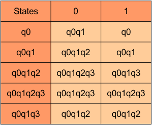
In the above DFA Table
- State Column Contains: “q0”, “q0q1” , “q0q1q2”, “q0q1q2q3“, “q0q1q3“
- Input columns contain: “q0”, “q0q1”, “q0q1q2”, “q0q1q2q3“, “q0q1q3“
At this stage, no new state remains. The DFA table is one step away to complete.
Step 3.3: State “q3” was the final state in the NFA Table. That’s why all those states will be the final states where “q3” is present in the DFA state column. Simply mark with “*” to represent the final state.
Here is the complete DFA transition table with its final states
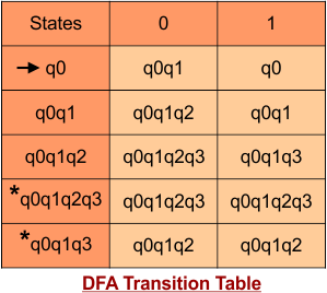
Step 4: Now draw DFA according to the DFA transition table
The following is the DFA machine that derives from the given NFA.

NFA to DFA Conversion Example 7.2
Step 01: Draw NFA Graph
The following is the NFA graph that needs to be converted to a DFA.
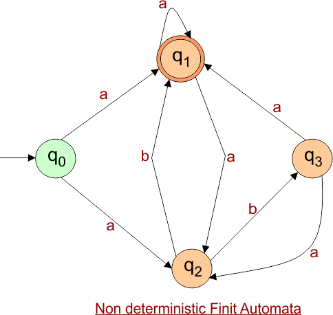
Step 02: Draw the NFA Transition Table.
The NFA transition table of the above NFA is given below
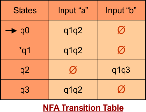
Step 03: Conversion of NFA to DFA Transition Table
Step 3.1:Select the first two rows of the NFA transition table, which will become the first two rows of the DFA transition table.
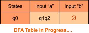
Step 3.2: Only “q0” exists in the state column of the DFA. However, the state “q1q2” occurs in the DFA table but does not appear in the state column. Therefore, we should simply add this state to the state column. The transitions for “q1q2” are given below
Transition at state “q1q2” against both inputs “0” and “1”
For input “0”
δ([q1q2], 0) = δ(q1, 0) ∪ δ(q2, 0)
= {q1q2} ∪ {ϕ}
= {q1q2}
For input “1”
δ([q1q2], 1) = δ(q1, 1) ∪ δ(q2, 1)
= {ϕ} ∪ {q1q3}
= {q1q3}
The Update DFA Table is given below
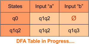
Repeat Step 3.2: State “q0” and “q1q2” exist in the state column of the DFA. However, the state “q1q3” occurs in the DFA table but does not appear in the state column. Therefore, we should simply add these states to the state column.
Transition at state “q1q3” is given below
For input “0”
δ([q1q3], 0) = δ(q1, 0) ∪ δ(q3, 0)
= {q1q2} ∪ {q1q2}
= {q1q2}
For input “1”
δ([q1q3], 1) = δ(q1, 1) ∪ δ(q3, 1)
= {ϕ} ∪ {ϕ}
= {ϕ}
The Update DFA Table is given below
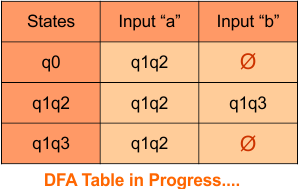
Repeat Step 3.2: State “q0”, “q1q2“, and “q1q3” exist in the state column of the DFA.. No new state exists in the DFA table, except ϕ. Transition at “ϕ” against both inputs “0” and “1” is given below
For input “0”
δ([ϕ], 0) = {ϕ}
For input “1”
δ([ϕ], 1) = {ϕ}
The Update DFA Table is given below
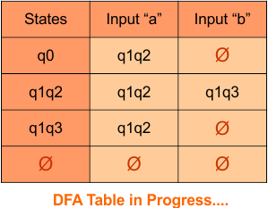
Step 3.3: At this stage, all newly generated states in the DFA table are executed successfully for their transitions, so the DFA table is ready.
Important: As q1 was the final state in NFA Table. That’s why, all those states will be the final states where q1 is present. Simply mark with “*” to represent the final state.
So, the following is the updated table of the DFA with its final states
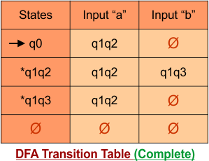
Step 4: Now draw the DFA according to the DFA Transition Table
According to the DFA transition table, we can generate the following DFA diagram.
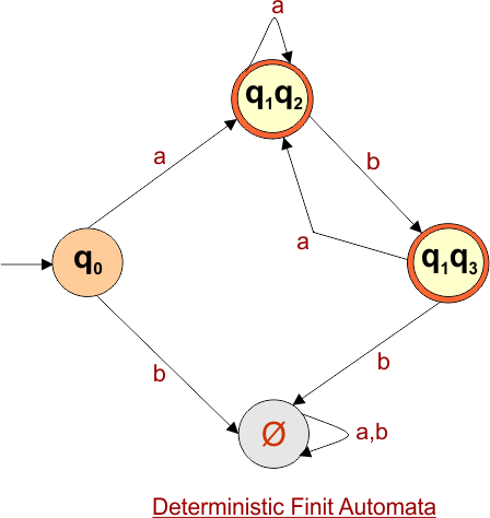
NFA to DFA Conversion Example 7.3
Step 01: Draw NFA Graph
The following is the NFA graph that needs to be converted to a DFA.
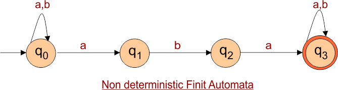
Step 02: Draw the NFA Transition Table.
The NFA transition table of the above NFA is given below
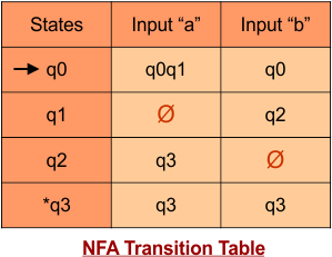
Step 03: Conversion of NFA to DFA Transition Table
Step 3.1:Select the first two rows of the NFA transition table, which will become the first two rows of the DFA transition table.
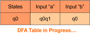
Step 3.2: Only “q0” exists in the state column of the DFA. However, the state “q0q1” occurs in the DFA table but does not appear in the state column. Therefore, we should simply add this state to the state column. The transitions for “q0q1” are given below
Transition at state “q0q1” against both inputs “a” and “b”
For input “a”
δ([q0q1], a) = δ(q0, a) ∪ δ(q1, a)
= {q0q1} ∪ {ϕ}
= {q0q1}
For input “b”
δ([q0q1], b) = δ(q0, b) ∪ δ(q1, b)
= {q0} ∪ {q2}
= {q0q2}
The Update DFA Table is given below
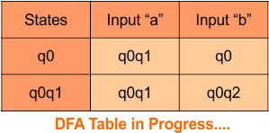
Repeat Step 3.2: State “q0” and “q0q1” exist in the state column of the DFA. However, the state “q0q2” occurs in the DFA table but does not appear in the state column. Therefore, we should simply add these states to the state column.
Transition at state “q0q2” is given below
For input “a”
δ([q0q2], a) = δ(q0, a) ∪ δ(q2, a)
= {q0q1} ∪ {q3}
= {q0q1q3}
For input “b”
δ([q0q2], b) = δ(q0, b) ∪ δ(q2, b)
= {q0} ∪ {ϕ}
= {q0}
The Update DFA Table is given below
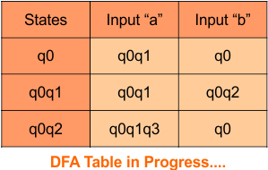
Repeat Step 3.2: State “q0”, “q0q1“, and “q0q2” exist in the state column of the DFA. However, the state “q0q1q3” occurs in the DFA table but does not appear in the state column. Therefore, we should simply add these states to the state column.
Transition at state “q0q1q3” is given below
For input “a”
δ([q0q1q3], a) = δ(q0, a) ∪ δ(q1, a) ∪ δ(q3, a)
= {q0q1} ∪ {ϕ} ∪ {q3}
= {q0q1q3}
For input “b”
δ([q0q1q3], b) = δ(q0, b) ∪ δ(q1, b) ∪ δ(q3, b)
= {q0} ∪ {q2} ∪ {q3}
= {q0q2q3}
The Update DFA Table is given below
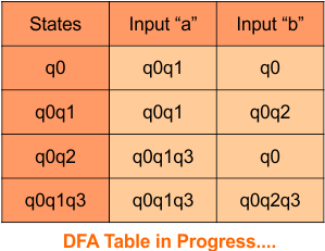
Repeat Step 3.2: State “q0”, “q0q1“, “q0q2”, and “q0q1q3” exist in the state column of the DFA. However, the state “q0q2q3” occurs in the DFA table but does not appear in the state column. Therefore, we should simply add these states to the state column.
Transition at state “q0q2q3” is given below
For input “a”
δ([q0q2q3], a) = δ(q0, a) ∪ δ(q2, a) ∪ δ(q3, a)
= {q0q1} ∪ {q3} ∪ {q3}
= {q0q1q3}
For input “b”
δ([q0q2q3], b) = δ(q0, b) ∪ δ(q2, b) ∪ δ(q3, b)
= {q0} ∪ {ϕ} ∪ {q3}
= {q0q3}
The Update DFA Table is given below
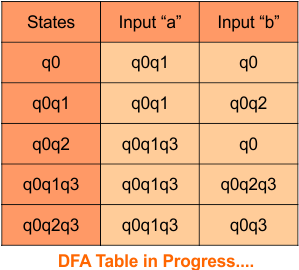
Repeat Step 3.2: State “q0”, “q0q1“, “q0q2″,”q0q1q3” and “q0q2q3” exist in the state column of the DFA. However, the state “q0q3” occurs in the DFA table but does not appear in the state column. Therefore, we should simply add these states to the state column.
Transition at state “q0q3” is given below
For input “a”
δ([q0q3], a) = δ(q0, a) ∪ δ(q3, a)
= {q0q1} ∪ {q3}
= {q0q1q3}
For input “b”
δ([q0q3], b) = δ(q0, b) ∪ δ(q3, b)
= {q0} ∪ {q3}
= {q0q3}
The Update DFA Table is given below
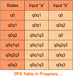
Step 3.3: At this stage, all newly generated states in the DFA table are executed successfully for their transitions, so the DFA table is ready.
Important: As q3 was the final state in NFA Table. That’s why, all those states will be the final states where q3 is present. Simply mark with “*” to represent the final state.
So, the following is the updated table of the DFA with its final states
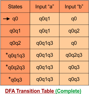
Step 4: Now draw the DFA according to the DFA Transition Table
According to the DFA transition table, we can generate the following DFA diagram.
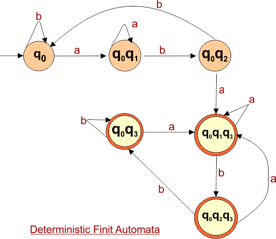
NFA to DFA Conversion Example 7.4
Step 01: Draw NFA Graph
The graph below represents an NFA that needs conversion into a DFA.
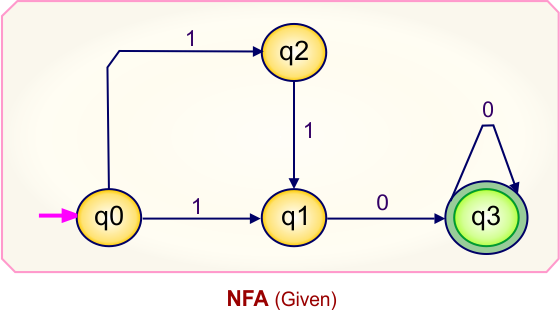
Step 02: Draw the NFA Transition Table.
The table below presents the transition table of the NFA derived from the given NFA.
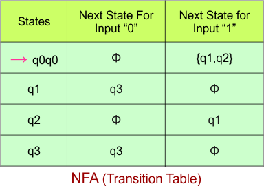
Step 03: Conversion of NFA to DFA Transition Table
Let’s begin converting the NFA transition table to the DFA transition table.
Step 3.1: Select the first two rows of the NFA transition table to form the initial two rows of the DFA transition table below.
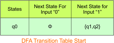
In the above DFA Table
- State Column Contains: “q0”
- Input columns contain: “q0”, “q1q2”
Step 3.2: State “q1q2” is a new state because it appears in the input columns of the DFA but does not exist in the state column. Add “q1q2” to the state column along with its transitions.
Transition calculations at state “q1q2”
For input “0”
δ([q1q2], 0) = δ(q1, 0) ∪ δ(q2, 0)
= {q3} ∪ {q}
= {q3}
For input “1”
δ([q1q2], 1) = δ(q1, 1) ∪ δ(q2, 1)
= {ϕ} ∪ {q1}
= {q1}
The updated DFA table is given below.
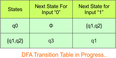
In the above DFA Table
- State Column Contains: “q0”, “q1q2”
- Input columns contain: “q0”, “q1q2″,”q3”, “q1”
Repeat Step 3.2: States “q3” and “q1” are new states because they are present in the DFA’s input columns but do not exist in the state column. Add states “q3” and “q1” along with their transitions to the state column.
Transition at state “q3“
For input “0”
δ(q3, 0) = {q3}
For input “1”
δ(q3, 1) = {ϕ}
Transition at state “q1“
For input “0”
δ(q1, 0) = {q3}
For input “1”
δ(q1, 1) = {ϕ}
The updated DFA table is given below.
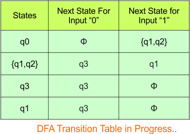
In the above DFA Table
- State Column Contains: “q0”, “q1q2”, “q3”, “q1”
- Input columns contain: “q0”, “q1q2”, “q3”, “q1”
Repeat Step 3.2: No new states exist in the DFA table, except ϕ. The transition at “ϕ” for all inputs will always remain at “ϕ”. The updated DFA table is given below.
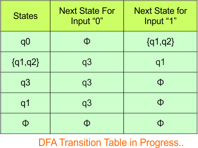
At this stage, no new states remain for the state column. The DFA table is just one step away from completion.
Step 3.3: State “q3” was the final state in the NFA table. Therefore, all states will be final states where “q3” appears in the DFA state column. Simply mark these states with “*” to indicate they are final states.
Here is the updated DFA table, which includes all of its final states.
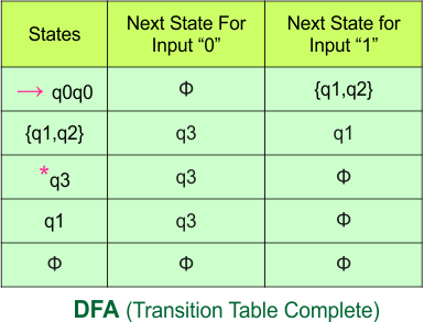
Step 4: Now draw the DFA according to the DFA transition table
The following is the converted Deterministic Finite Automaton (DFA) derived from the given Nondeterministic Finite Automaton (NFA).
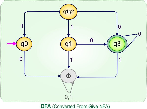
NFA to DFA Conversion Example 7.5
Step 01: Draw NFA Graph
The following is the NFA graph that needs to be converted to a DFA.
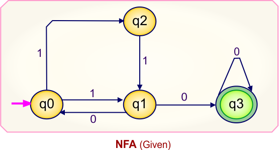
Step 02: Draw the NFA Transition Table.
The following is the NFA transition table, which is derived from the given NFA.
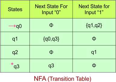
Note: All transitions are made according to the NFA transition table to get the DFA transition table.
Step 03: Conversion of NFA to DFA Transition Table
Let’s start the conversion of the NFA transition table to the DFA transition Table.
Step 3.1: Select the first two rows of the NFA transition table, which will become the first two rows of the DFA transition table given below.
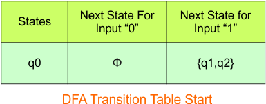
In the above DFA Table
- State Column Contains: “q0”
- Input columns contain: “q1q2”
Step 3.2: The state “q1q2” is newly added because it appears in the input columns of the DFA but does not exist in the state column. Include “q1q2” in the state column along with its transitions.
Transition calculations at state “q1q2”
For input “0”
δ([q1q2], 0) = δ(q1, 0) ∪ δ(q2, 0)
= {q0q3} ∪ {}
= {q0q3}
For input “1”
δ([q1q2], 1) = δ(q1, 1) ∪ δ(q2, 1)
= {} ∪ {q1}
= {q1}
The updated DFA table is given below.
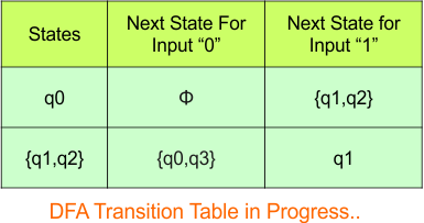
In the above DFA Table
- State Column Contains: “q0”, “q1q2”
- Input columns contain: “q1q2”, “q0q3”, “q1”
Repeat Step 3.2: States “q0q3” and “q1” are new states because they are present in the DFA’s input columns but do not exist in the state column. Add states “q0q3” and “q1” along with their transitions to the state column.
Transition calculations at state “q0q3”
For input “0”
δ([q0q3], 0) = δ(q0, 0) ∪ δ(q3, 0)
= {} ∪ {q3}
= {q3}
For input “1”
δ([q0q3], 1) = δ(q0, 1) ∪ δ(q3, 1)
= {q1q2} ∪ {}
= {q1q2}
Transition calculations at state “q1”
For input “0”
δ([q1], 0) = {q0q3}
For input “1”
δ([q1], 1 = {}
The updated DFA table is given below.
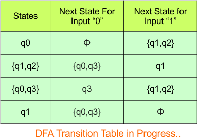
In the above DFA Table
- State Column Contains: “q0”, “q1q2″,”q0q3”, “q1”
- Input columns contain: “q0”, “q1q2″,”q0q3”, “q1”, “q3”
Repeat Step 3.2: The state “q3” is newly added because it appears in the input columns of the DFA but does not exist in the state column. Include “q3” in the state column along with its transitions.
Transition calculations at state “q3”
For input “0”
δ([q3], 0) = {q3}
For input “1”
δ([q3], 1 = {}
The updated DFA table is given below.
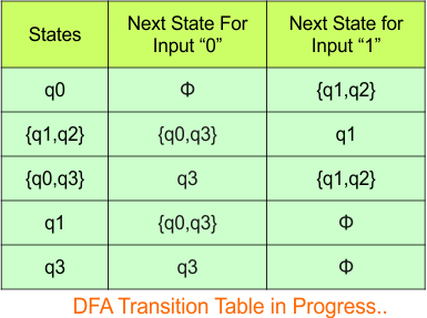
In the above DFA Table
- State Column Contains: “q0”, “q1q2″,”q0q3”, “q1”, “q3”
- Input columns contain: “q0”, “q1q2″,”q0q3”, “q1”, “q3”
Repeat Step 3.2: No new state exists in the DFA table, except ϕ. Transition at “ϕ” against all inputs will always stay at “ϕ”. The updated DFA Table is given below
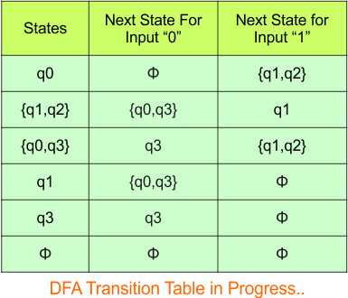
Step 3.3: State “q3” was the final state in the NFA Table. That’s why all those states will be the final states where “q3” is present in the DFA state column. Simply mark with “*” to represent the final state.
The following is the updated DFA table with all its final states
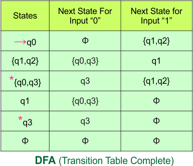
Step 4: Now draw the DFA according to the DFA transition table
The following is the converted DFA from the given NFA.
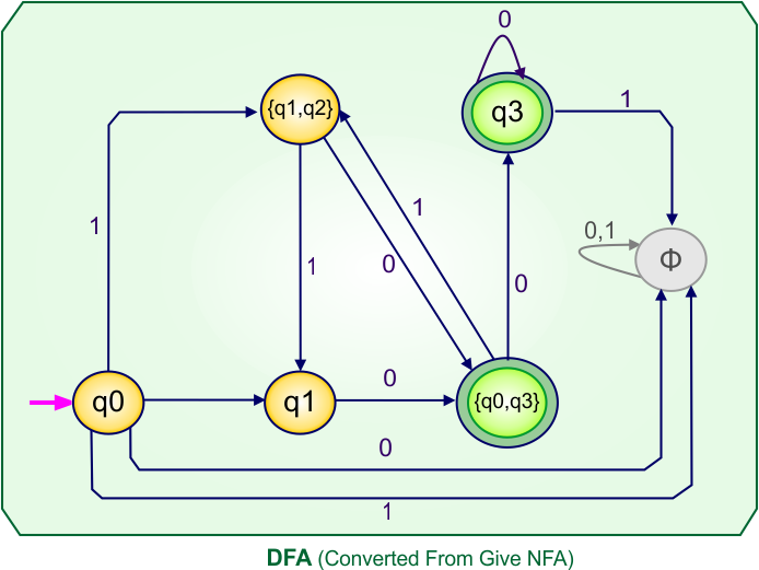
NFA to DFA Conversion Example 7.6
Step 01: Draw NFA Graph
The graph below represents an NFA that needs conversion into a DFA.
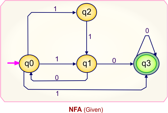
Step 02: Draw the NFA Transition Table.
The table below presents the transition table of the NFA derived from the given NFA.
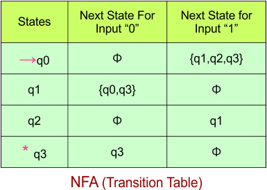
Step 03: Conversion of NFA to DFA Transition Table
Let’s begin converting the NFA transition table to the DFA transition table.
Step 3.1: Select the first two rows of the NFA transition table to form the initial two rows of the DFA transition table below.
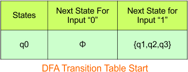
In the above DFA Table
- State Column Contains: “q0”
- Input columns contain: “q1q2q3”
Step 3.2: State “q1q2q3” is a new state because it appears in the input columns of the DFA but does not exist in the state column. Add “q1q2q3” to the state column along with its transitions.
Transition calculations at state “q1q2q3”
For input “0”
δ([q1q2q3], 0) = δ(q1, 0) ∪ δ(q2, 0) ∪ δ(q3, 0)
= {q0q3} ∪ {} ∪ {q3}
= {q0q3}
For input “1”
δ([q1q2q3], 1) = δ(q1, 1) ∪ δ(q2, 1) ∪ δ(q3, 1)
= {} ∪ {q1} ∪ {}
= {q1}
The updated DFA table is given below.
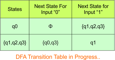
In the above DFA Table
- State Column Contains: “q0”, “q1q2q3”
- Input columns contain: “q1q2q3”, “q0q3″,”q1”
Repeat Step 3.2: States “q0q3” and “q1” are new states because they are present in the DFA’s input columns but do not exist in the state column. Add states “q0q3” and “q1” along with their transitions to the state column.
Transition calculations at state “q0q3”
For input “0”
δ([q0q3], 0) = δ(q0, 0) ∪ δ(q3, 0)
= {} ∪ {q3}
= {q3}
For input “1”
δ([q0q3], 1) = δ(q0, 1) ∪ δ(q3, 1)
= {q1q2q3} ∪ {}
= {q1q2q3}
Transition calculations at state “q1”
For input “0”
δ([q1], 0) = {q0q3}
For input “1”
δ([q1], 1) = {}
The updated DFA table is given below.
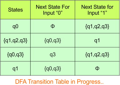
In the above DFA Table
- State Column Contains: “q0”, “q1q2q3”, “q0q3″,”q1”
- Input columns contain: “q1q2q3”, “q0q3″,”q1”, “q3”
Repeat Step 3.2: “q3” is a new state because it is present in the input columns of the DFA but does not exist in the state column. Put “q3” in the state column along with their transitions.
Transition calculations at state “q3”
For input “0”
δ([q3], 0) = {q3}
For input “1”
δ([q3], 1) = {}
The updated DFA table is given below.

Repeat Step 3.2: No new states exist in the DFA table, except ϕ. The transition at “ϕ” for all inputs will always remain at “ϕ”. The updated DFA table is given below.
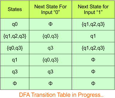
Step 3.3: State “q” was the final state in the NFA table. Therefore, all states will be final states where “q” appears in the DFA state column. Simply mark these states with “*” to indicate they are final states.
Here is the updated DFA table, which includes all of its final states.
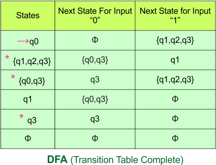
Step 4: Now draw the DFA according to the DFA transition table
The following is the converted Deterministic Finite Automaton (DFA) derived from the given Nondeterministic Finite Automaton (NFA).
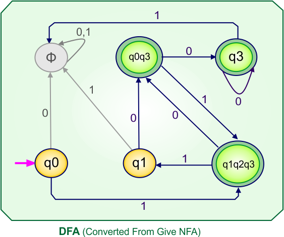
NFA to DFA Category-08 Examples: 4-States, 3-Input Symbols
Category 08 covers NFA to DFA conversions for machines with four states over the three input alphabets {a,b,c}.
NFA to DFA Conversion Example 8.1
Step 01: Draw NFA Graph
The following is the NFA graph that needs to be converted to a DFA.
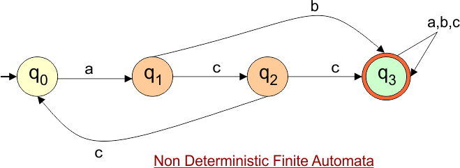
Step 02: Draw the NFA Transition Table.
The NFA transition table of the above NFA is given below
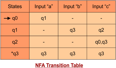
Step 03: Conversion of NFA to DFA Transition Table
Step 3.1:Select the first two rows of the NFA transition table, which will become the first two rows of the DFA transition table.
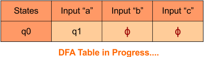
Step 3.2: Only “q0” exists in the state column of the DFA. However, the state “q1” occurs in the DFA table but does not appear in the state column. Therefore, we should simply add this state to the state column. The transitions for “q1” are given below
Transition at state “q1” against all inputs “a”, “b” and “c”
For input “a”
δ([q1], a) = {ϕ}
For input “b”
δ([q1], b) = {q3}
For input “c”
δ([q1], c) = {q2}
The updated DFA Table is given below
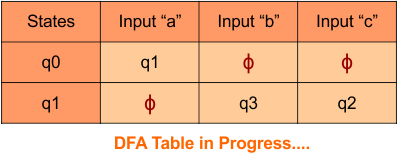
Repeat Step 3.2: State “q0” and “q1” exist in the state column of the DFA. However, the states “q2” and “q3” occur in the DFA table but do not appear in the state column. Therefore, we should add these states to the state column.
Transition at state “q2” against all inputs “a”, “b”, and “c”
For input “a”
δ([q1], a) = {ϕ}
For input “b”
δ([q1], b) = {ϕ}
For input “c”
δ([q1], c) = {q0q3}
Transition at state “q3” against all inputs “a”, “b” and “c”
For input “a”
δ([q1], a) = {q3}
For input “b”
δ([q1], b) = {q3}
For input “c”
δ([q1], c) = {q3}
The updated DFA Table is given below
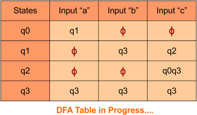
Repeat Step 3.2: State “q0”, “q1”, “q2”, and “q3” exist in the state column of the DFA. However, the state “q0q3” occurs in the DFA table but does not appear in the state column. Therefore, we should add these states to the state column.
Transition at state “q0q3” against all inputs “a”, “b”, and “c” is given below
For input “a”
δ([q0q3], a) = δ(q0, a) ∪ δ(q3, a)
= {q1} ∪ {q3}
= {q1q3}
For input “b”
δ([q0q3], b) = δ(q0, b) ∪ δ(q3, b)
= {ϕ} ∪ {q3}
= {q3}
For input “c”
δ([q0q3], c) = δ(q0, c) ∪ δ(q3, c)
= {ϕ} ∪ {q3}
= {q3}
The updated DFA Table is given below
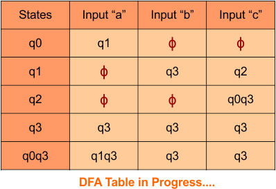
Repeat Step 3.2: State “q0”, “q1”, “q2”, “q3”, and “q0q3” exist in the state column of the DFA. However, the state “q1q3” occurs in the DFA table but does not appear in the state column. Therefore, we should add these states to the state column.
Transition at state “q1q3” against all inputs “a”, “b”, and “c” is given below
For input “a”
δ([q1q3], a) = δ(q1, a) ∪ δ(q3, a)
= {ϕ} ∪ {q3}
= {q3}
For input “b”
δ([q1q3], b) = δ(q1, b) ∪ δ(q3, b)
= {q3} ∪ {q3}
= {q3}
For input “c”
δ([q1q3], c) = δ(q1, c) ∪ δ(q3, c)
= {q2} ∪ {q3}
= {q2q3}
The updated DFA Table is given below
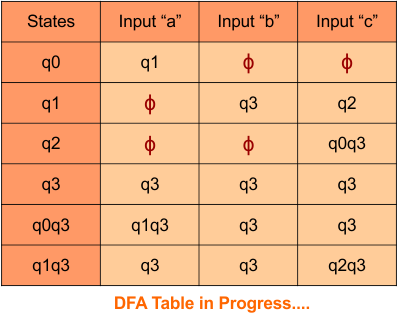
Repeat Step 3.2: State “q0”, “q1”, “q2”, “q3”, “q0q3”, and “q1q3” exist in the state column of the DFA. However, the state “q2q3” occurs in the DFA table but does not appear in the state column. Therefore, we should add these states to the state column.
Transition at state “q2q3” against all inputs “a”, “b”, and “c” is given below
For input “a”
δ([q2q3], a) = δ(q2, a) ∪ δ(q3, a)
= {ϕ} ∪ {q3}
= {q3}
For input “b”
δ([q2q3], b) = δ(q2, b) ∪ δ(q3, b)
= {ϕ} ∪ {q3}
= {q3}
For input “c”
δ([q2q3], c) = δ(q2, c) ∪ δ(q3, c)
= {q0q3} ∪ {q3}
= {q0q3}
The updated DFA Table is given below
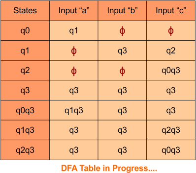
Step 3.3: At this stage, all newly generated states in the DFA table are executed successfully for their transitions, so the DFA table is ready.
Important: As q3 was the final state in NFA Table. That’s why, all those states will be the final states where q3 is present. Simply mark with “*” to represent the final state.
So, the following is the updated table of the DFA with its final states
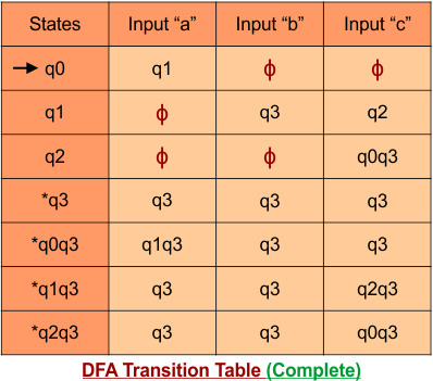
Step 4: Now draw the DFA according to the DFA Transition Table
According to the DFA transition table, we can generate the following DFA diagram.
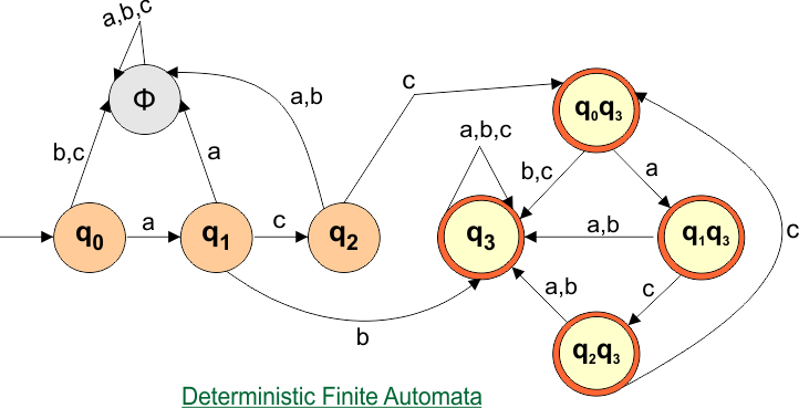
NFA to DFA Conversion Example 8.2
Step 01: Draw NFA Graph
The following is the NFA graph that needs to be converted to a DFA.
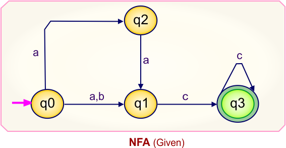
Step 02: Draw the NFA Transition Table.
The NFA transition table of the above NFA is given below
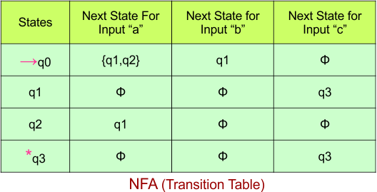
Step 03: Conversion of NFA to DFA Transition Table
Step 3.1: Select the first two rows of the NFA transition table, which will become the first two rows of the DFA transition table.
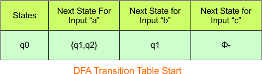
In the above DFA Table
- State Column Contains: “q0”
- Input columns contain: “q0”, “q1q2”, “q1”
Step 3.2: States “q1q2” and “q1” are new states because they are present in the DFA’s input columns but do not exist in the state column. Add states “q1q2” and “q1” along with their transitions to the state column.
Transition calculations at state “q1q2”
For input “a”
δ([q1q2], a) = δ(q1, a) ∪ δ(q2, a)
= {ϕ} ∪ {q1}
= {q1}
For input “b”
δ([q1q2], b) = δ(q1, b) ∪ δ(q2, b)
= {ϕ} ∪ {ϕ}
= {ϕ}
For input “c”
δ([q1q2], c) = δ(q1, c) ∪ δ(q2, c)
= {q3} ∪ {ϕ}
= {q3}
Transition calculations at state “q1”
For input “a”
δ(q1, a) = {ϕ}
For input “b”
δ(q1, b) = {ϕ}
For input “c”
δ(q1, c) = {q3}
Hence, the updated DFA table is given below.
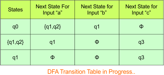
In the above DFA Table
- State Column Contains: “q0”, “q1q2”, “q1”
- Input columns contain: “q0”, “q1q2”, “q1”, “q3”
Repeat Step 3.2: “q3” is a new state because it is present in the input columns of the DFA but does not exist in the state column. Put “q3” in the state column along with their transitions.
Transition calculations at state “q3”
For input “a”
δ(q3, a) = {ϕ}
For input “b”
δ(q3, b) = {ϕ}
For input “c”
δ(q3, c) = {q3}
The updated DFA Table is given below
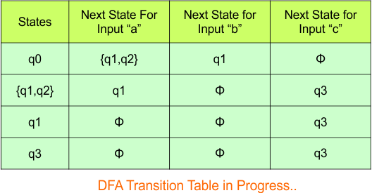
In the above DFA Table
- State Column Contains: “q0”, “q1q2”, “q1”, “q3”
- Input columns contain: “q0”, “q1q2”, “q1”, “q3”
Repeat Step 3.2: No new state exists in the DFA table, except ϕ. Transition at “ϕ” against all inputs will always stay at “ϕ”. The updated DFA Table is given below
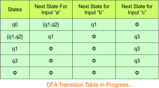
At this stage, no new state remains for the state column. The DFA table is one step away from being complete.
Step 3.3: At this stage, all newly generated states in the DFA table are executed successfully for their transitions, so the DFA table is ready.
Important: As “q3” was the final state in NFA Table. That’s why, all those states will be the final states where “q3” is present. Simply mark with “*” to represent the final state.
So, the following is the updated table of the DFA with its final states
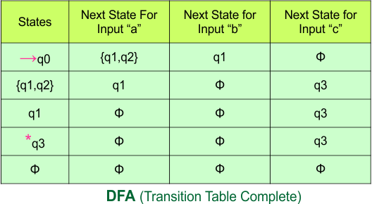
Step 4: Now draw the DFA according to the DFA Transition Table
According to the DFA transition table, we can generate the following DFA diagram.
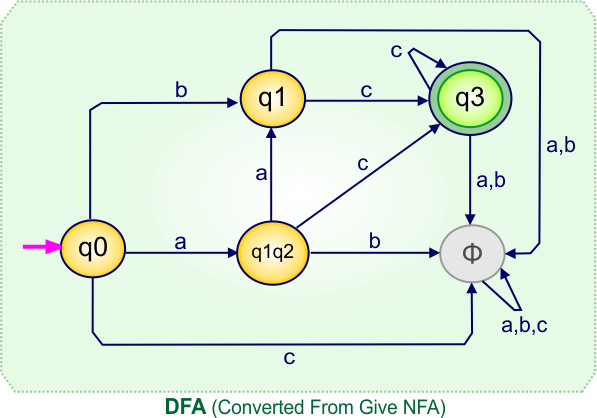
NFA to DFA Conversion Example 8.3
Step 01: Draw NFA Graph
The following is the NFA graph that needs to be converted to a DFA.
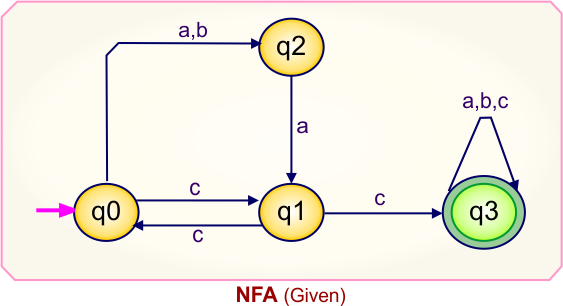
Step 02: Draw the NFA Transition Table.
The NFA transition table of the above NFA is given below
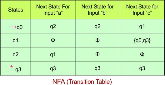
Step 03: Conversion of NFA to DFA Transition Table
Step 3.1: Select the first two rows of the NFA transition table, which will become the first two rows of the DFA transition table.
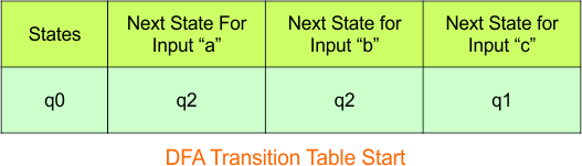
In the above DFA Table
- State Column Contains: “q0”
- Input columns contain: “q1”, “q2”
Step 3.2: State “q1” and “q2” are new states because these are present in the DFA’s input columns but do not exist in the state column. Put “q1” and “q2” in the state column along with their transitions.
Transition at state “q1“
For input “a”
δ([q1], a) = {}
For input “b”
δ([q1], b) = {}
For input “c”
δ([q1], c) = {q0q3}
Transition at state “q2“
For input “a”
δ([q2], a) = {q1}
For input “b”
δ([q2], b) = {}
For input “c”
δ([q2], c) = {}
Hence, the updated DFA table is given below.
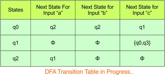
In the above DFA Table
- State Column Contains: “q0”, “q1”, “q2”
- Input columns contain: “q1”, “q2”, “q0q3”
Repeat Step 3.2: “q0q3” is a new state because it is present in the input columns of the DFA but does not exist in the state column. Put “q0q3” in the state column along with their transitions.
Transition calculations at state “q0q3”
For input “a”
δ([q0q3], a) = δ(q0, a) ∪ δ(q3, a)
= {q2} ∪ {q3}
= {q2q3}
For input “b”
δ([q0q3], b) = δ(q0, b) ∪ δ(q3, b)
= {q2} ∪ {q3}
= {q2q3}
For input “c”
δ([q0q3], c) = δ(q0, c) ∪ δ(q3, c)
= {q1} ∪ {q3}
= {q1q3}
Hence, the updated DFA table is given below.
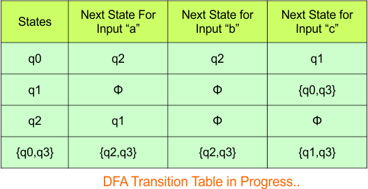
In the above DFA Table
- State Column Contains: “q0”, “q1”, “q2”, “q0q3”
- Input columns contain: “q1”, “q2”, “q0q3”, “q2q3”, “q1q3”
Repeat Step 3.2: States “q2q3” and “q1q3” are new states because they are present in the DFA’s input columns but do not exist in the state column. Add states “q2q3” and “q1q3” along with their transitions to the state column.
Transition calculations at state “q2q3”
For input “a”
δ([q2q3], a) = δ(q2, a) ∪ δ(q3, a)
= {q1} ∪ {q3}
= {q1q3}
For input “b”
δ([q2q3], b) = δ(q2, b) ∪ δ(q3, b)
= {} ∪ {q3}
= {q3}
For input “c”
δ([q2q3], c) = δ(q2, c) ∪ δ(q3, c)
= {} ∪ {q3}
= {q3}
Transition calculations at state “q1q3”
For input “a”
δ([q1q3], a) = δ(q1, a) ∪ δ(q3, a)
= {} ∪ {q3}
= {q3}
For input “b”
δ([q1q3], b) = δ(q1, b) ∪ δ(q3, b)
= {} ∪ {q3}
= {q3}
For input “c”
δ([q1q3], c) = δ(q3, c) ∪ δ(q3, c)
= {q0q3} ∪ {q3}
= {q0q3}
Hence, the updated DFA table is given below.
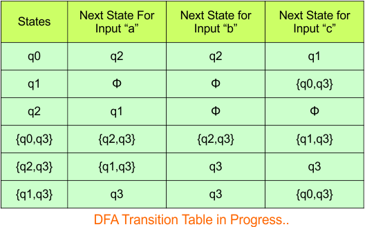
In the above DFA Table
- State Column Contains: “q0”, “q1”, “q2”, “q0q3”, “q2q3”, “q1q3”
- Input columns contain: “q1”, “q2”, “q0q3”, “q2q3”, “q1q3”, “q3”
Repeat Step 3.2: “q3” is a new state because it is present in the input columns of the DFA but does not exist in the state column. Put “q3” in the state column along with its transitions.
Transition at state “q3“
For input “a”
δ([q3], c) = {q3}
For input “b”
δ([q3], c) = {q3}
For input “c”
δ([q3], c) = {q3}
In the above DFA Table
- State Column Contains: “q0”, “q1”, “q2”, “q0q3”, “q2q3”, “q1q3”, “q3”
- Input columns contain: “q1”, “q2”, “q0q3”, “q2q3”, “q1q3”, “q3”
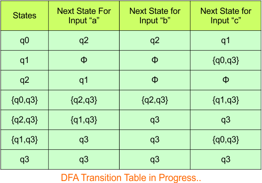
Repeat Step 3.2:No new state exists in the DFA table, except ϕ. Transition at “ϕ” against all inputs will always stay at “ϕ”. The updated DFA Table is given below
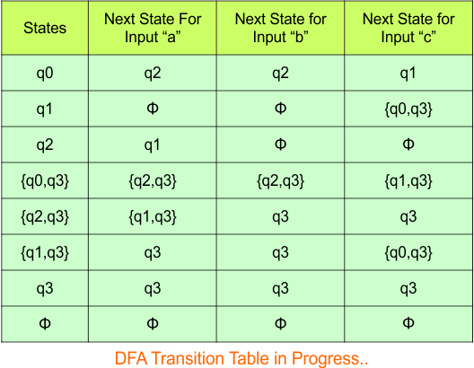
Step 3.3: At this stage, all newly generated states in the DFA table are executed successfully for their transitions, so the DFA table is ready.
Important: As “q3” was the final state in NFA Table. That’s why, all those states will be the final states where “q3” is present. Simply mark with “*” to represent the final state.
So, the following is the updated table of the DFA with its final states
![]()
Step 4: Now draw the DFA according to the DFA Transition Table
According to the DFA transition table, we can generate the following DFA diagram.
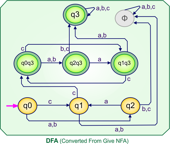
NFA to DFA Conversion Example 8.4
Step 01: Draw NFA Graph
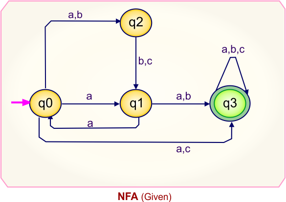
The following is the NFA graph that needs to be converted to a DFA.
Step 02: Draw the NFA Transition Table.
The NFA transition table of the above NFA is given below
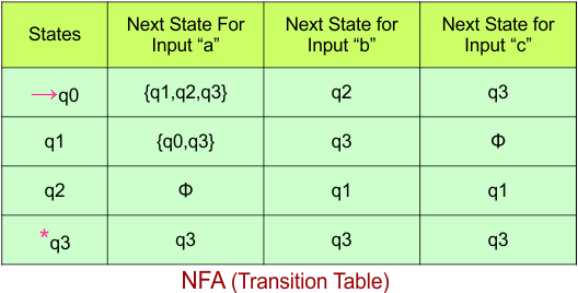
Step 03: Conversion of NFA to DFA Transition Table
Step 3.1: Select the first two rows of the NFA transition table, which will become the first two rows of the DFA transition table.
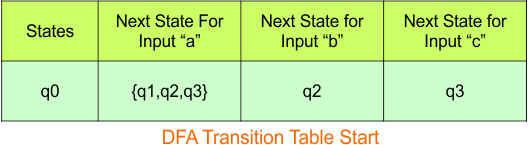
In the above DFA Table
- State Column Contains: “q0”
- Input columns contain: “q1q2q3”, “q2”, “q3”
Repeat Step 3.2: States “q1q2q3”, “q2”, and “q3” are new states because they are present in the DFA’s input columns but do not exist in the state column. Add states “q1q2q3”, “q2”, and “q3” along with their transitions to the state column.
Transition at state “q2”
For input “a”
δ([q2], a) = {}
For input “b”
δ([q2], b) = {q1}
For input “c”
δ([q2], c) = {q1}
Transition at state “q3”
For input “a”
δ([q3], a) = {q3}
For input “b”
δ([q3], b) = {q3}
For input “c”
δ([q3], c) = {q3}
Transition at state “q1q2q3”
For input “a”
δ([q1q2q3], a) = δ(q1, a) ∪ δ(q2, a) ∪ δ(q3, a)
= {q0q3} ∪ {} ∪ {q3}
= {q0q3}
For input “b”
δ([q1q2q3], b) = δ(q1, b) ∪ δ(q2, b) ∪ δ(q3, b)
= {q3} ∪ {q1} ∪ {q3}
= {q1q3}
For input “c”
δ([q1q2q3], c) = δ(q1, c) ∪ δ(q2, c) ∪ δ(q3, c)
= {} ∪ {q1} ∪ {q3}
= {q1q3}
Hence, the updated DFA table is given below.
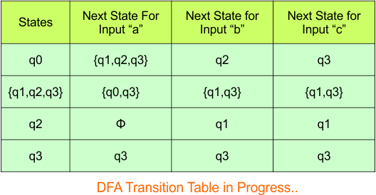
In the above DFA Table
- State Column Contains: “q0″,”q1q2q3”, “q2”, “q3”
- Input columns contain: “q1q2q3”, “q2”, “q3”, “q1″,”q1q3”, “q0q3”
Repeat Step 3.2: States “q1”, “q1q3”, and “q0q3” are new states because they are present in the DFA’s input columns but do not exist in the state column. Add states “q1”, “q1q3”, and “q0q3” along with their transitions to the state column .
Transition at state “q1”
For input “a”
δ([q1], a) = {q0q3}
For input “b”
δ([q1], b) = {q3}
For input “c”
δ([q1], c) = {}
Transition calculations for state “q1q3”
For input “a”
δ([q1q3], a) = δ(q1, a) ∪ δ(q3, a)
= {q0q3} ∪ {q3}
= {q0q3}
For input “b”
δ([q1q3], b) = δ(q1, b) ∪ δ(q3, b)
= {q3} ∪ {q3}
= {q3}
For input “c”
δ([q1q3], c) = δ(q1, c) ∪ δ(q3, c)
= {} ∪ {q3}
= {q3}
Transition calculations for state “q0q3”
For input “a”
δ([q0q3], a) = δ(q0, a) ∪ δ(q3, a)
= {q1q2q3} ∪ {q3}
= {q1q2q3}
For input “b”
δ([q0q3], b) = δ(q0, b) ∪ δ(q3, b)
= {q2} ∪ {q3}
= {q2q3}
For input “c”
δ([q0q3], c) = δ(q0, c) ∪ δ(q3, c)
= {q3} ∪ {q3}
= {q3}
The updated DFA Table is given below
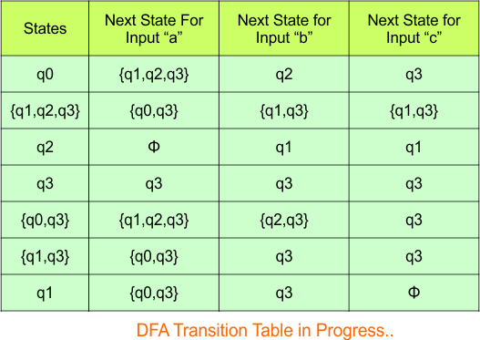
In the above DFA Table
- State Column Contains: “q0″,”q1q2q3”, “q2”, “q3”, “q0q3”, “q1q3”, “q1”
- Input columns contain: “q1q2q3”, “q2”, “q3”, “q1″,”q1q3”, “q0q3”, “q2q3”
Repeat Step 3.2: “q2q3” is a new state because it is present in the input columns of the DFA but does not exist in the state column. Put “q2q3” in the state column along with their transitions.
Transition calculations for state “q2q3”
For input “a”
δ([q2q3], a) = δ(q2, a) ∪ δ(q3, a)
= {} ∪ {q3}
= {q3}
For input “b”
δ([q2q3], b) = δ(q2, b) ∪ δ(q3, b)
= {q1} ∪ {q3}
= {q1q3}
For input “c”
δ([q2q3], c) = δ(q2, c) ∪ δ(q3, c)
= {q1} ∪ {q3}
= {q1q3}
The updated DFA Table is given below
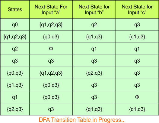
In the above DFA Table
- State Column Contains: “q0″,”q1q2q3”, “q2”, “q3”, “q0q3”, “q1q3”, “q1”, “q2q3”
- Input columns contain: “q1q2q3”, “q2”, “q3”, “q1″,”q1q3”, “q0q3”, “q2q3”
Repeat Step 3.2: No new state exists in the DFA table, except ϕ. Transition at “ϕ” against all inputs will always stay at “ϕ”. The updated DFA Table is given below
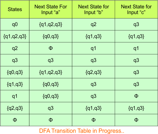
Step 3.3: At this stage, all newly generated states in the DFA table are executed successfully for their transitions, so the DFA table is ready.
Important: As “q3” was the final state in NFA Table. That’s why, all those states will be the final states where “q3” is present. Simply mark with “*” to represent the final state.
So, the following is the updated table of the DFA with its final states
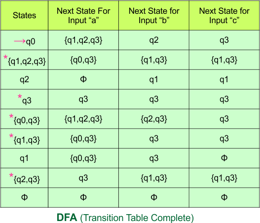
Step 4: Now draw the DFA according to the DFA Transition Table
According to the DFA transition table, we can generate the following DFA diagram
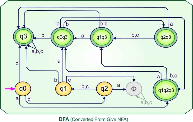
NFA to DFA Category-09 Examples: 4-States, 4-Input Symbols
Category 09 covers NFA to DFA conversions for machines with four states over the four input alphabets {a,b,c,d}.
NFA to DFA Conversion Example 9.1
Step 01: Draw NFA Graph
The following is the NFA graph that needs to be converted to a DFA.
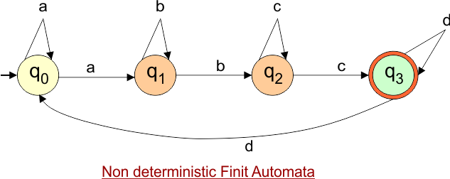
Step 02: Draw the NFA Transition Table.
The NFA transition table of the above NFA is given below
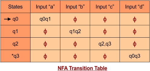
Step 03: Conversion of NFA to DFA Transition Table
Step 3.1:Select the first two rows of the NFA transition table, which will become the first two rows of the DFA transition table.
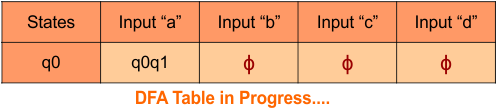
Step 3.2: Only “q0” exists in the state column of the DFA. However, the state “q0q1” occurs in the DFA table but does not appear in the state column. Therefore, we should simply add this state to the state column. The transitions for “q0q1” are given below
Transition at state “q0q1” against all inputs “a”, “b”, “c”, and “d” is given below
For input “a”
δ([q0q1], a) = δ(q0, a) ∪ δ(q1, a)
= {q0q1} ∪ {ϕ}
= {q0q1}
For input “b”
δ([q0q1], b) = δ(q0, b) ∪ δ(q1, b)
= {ϕ} ∪ {q1q2}
= {q1q2}
For input “c”
δ([q0q1], c) = δ(q0, c) ∪ δ(q1, c)
= {ϕ} ∪ {ϕ}
= {ϕ}
For input “d”
δ([q0q1], d) = δ(q0, d) ∪ δ(q1, d)
= {ϕ} ∪ {ϕ}
= {ϕ}
The updated DFA Table is given below
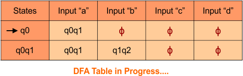
Step 3.2: State “q0” and “q0q1” exist in the state column of the DFA. However, the state “q1q2” occurs in the DFA table but does not appear in the state column. Therefore, we should simply add this state to the state column. The transitions for “q1q2” are given below
Transition at state “q1q2” against all inputs “a”, “b”, “c”, and “d” is given below
For input “a”
δ([q1q2], a) = δ(q1, a) ∪ δ(q2, a)
= {ϕ} ∪ {ϕ}
= {ϕ}
For input “b”
δ([q1q2], b) = δ(q1, b) ∪ δ(q2, b)
= {q1q2} ∪ {ϕ}
= {q1q2}
For input “c”
δ([q1q2], c) = δ(q1, c) ∪ δ(q2, c)
= {ϕ} ∪ {q2q3}
= {q2q3}
For input “d”
δ([q1q2], d) = δ(q1, d) ∪ δ(q2, d)
= {ϕ} ∪ {ϕ}
= {ϕ}
The updated DFA Table is given below
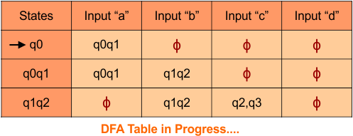
Step 3.2: State “q0”, “q0q1”, and “q1q2” exist in the state column of the DFA. However, the state “q2q3” occurs in the DFA table but does not appear in the state column. Therefore, we should simply add this state to the state column. The transitions for “q2q3” are given below
Transition at state “q2q3” against all inputs “a”, “b”, “c”, and “d” is given below
For input “a”
δ([q2q3], a) = δ(q2, a) ∪ δ(q3, a)
= {ϕ} ∪ {ϕ}
= {ϕ}
For input “b”
δ([q2q3], b) = δ(q2, b) ∪ δ(q3, b)
= {ϕ} ∪ {ϕ}
= {ϕ}
For input “c”
δ([q2q3], c) = δ(q2, c) ∪ δ(q3, c)
= {q2q3} ∪ {ϕ}
= {q2q3}
For input “d”
δ([q2q3], d) = δ(q2, d) ∪ δ(q3, d)
= {ϕ} ∪ {q0q3}
= {q0q3}
The updated DFA Table is given below
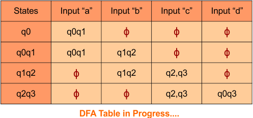
Step 3.2: State “q0”, “q0q1”, “q1q2”, and “q2q3” exist in the state column of the DFA. However, the state “q0q3” occurs in the DFA table but does not appear in the state column. Therefore, we should simply add this state to the state column. The transitions for “q0q3” are given below
Transition at state “q0q3” against all inputs “a”, “b”, “c”, and “d” is given below
For input “a”
δ([q0q3], a) = δ(q0, a) ∪ δ(q3, a)
= {q0q1} ∪ {ϕ}
= {q0q1}
For input “b”
δ([q0q3], b) = δ(q0, b) ∪ δ(q3, b)
= {ϕ} ∪ {ϕ}
= {ϕ}
For input “c”
δ([q0q3], c) = δ(q0, c) ∪ δ(q3, c)
= {ϕ} ∪ {ϕ}
= {ϕ}
For input “d”
δ([q0q3], d) = δ(q0, d) ∪ δ(q3, d)
= {ϕ} ∪ {q0q3}
= {q0q3}
The updated DFA Table is given below
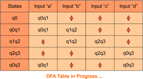
Step 3.3: At this stage, all newly generated states in the DFA table are executed successfully for their transitions, so the DFA table is ready.
Important: As q4 was the final state in NFA Table. That’s why, all those states will be the final states where q4 is present. Simply mark with “*” to represent the final state.
So, the following is the updated table of the DFA with its final states
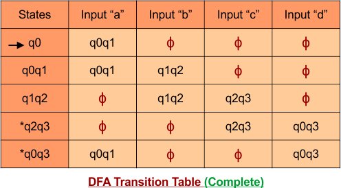
Step 4: Now draw the DFA according to the DFA Transition Table
According to the DFA transition table, we can generate the following DFA diagram.\
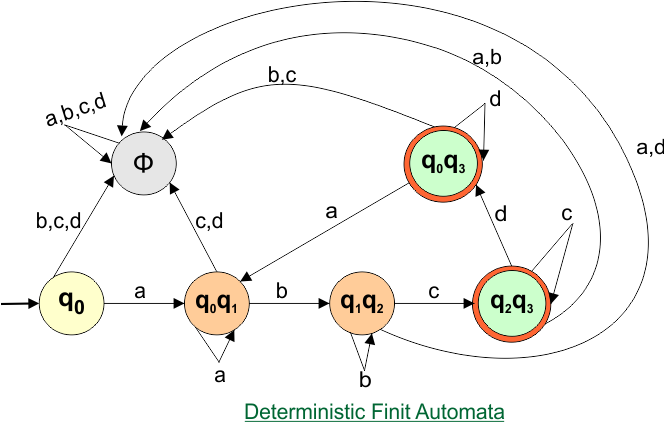
NFA to DFA Conversion Example 9.2
Step 01: Draw NFA Graph
The following is the NFA graph that needs to be converted to a DFA.
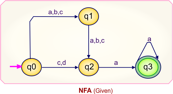
Step 02: Draw the NFA Transition Table.
The NFA transition table of the above NFA is given below
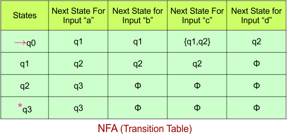
Step 03: Conversion of NFA to DFA Transition Table
Step 3.1:Select the first two rows of the NFA transition table, which will become the first two rows of the DFA transition table.
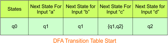
In the above DFA Table
- State Column Contains: “q0”
- Input columns contain: “q1”, “q1q2”, “q2”
Step 3.2: States “q1“, “q1q2“, and “q2” are new states because they are present in the DFA’s input columns but do not exist in the state column. Add states “q1“, “q1q2“, and “q2” along with their transitions to the state column.
Transition at state “q1“
For input “a”
δ([q1], a) = {q2}
For input “b”
δ([q1], b) = {q2}
For input “c”
δ([q1], c) = {q2}
For input “d”
δ([q1], d) = {}
Transition at state “q1q2”
For input “a”
δ([q1q2], a) = δ(q1, a) ∪ δ(q2, a)
= {q2} ∪ {q3}
= {q2q3}
For input “b”
δ([q1q2], b) = δ(q1, b) ∪ δ(q2, b)
= {q2} ∪ {}
= {q2}
For input “c”
δ([qq], c) = δ(q, c) ∪ δ(q, c)
= {q2} ∪ {}
= {q2}
For input “d”
δ([q1q2], d) = δ(q1, d) ∪ δ(q2, d)
= {} ∪ {}
= {}
Transition at state “q2“
For input “a”
δ([q2], a) = {q3}
For input “b”
δ([q2], b) = {}
For input “c”
δ([q2], c) = {}
For input “d”
δ([q2], d) = {}
The updated DFA Table is given below
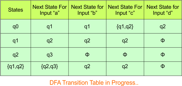
In the above DFA Table
- State Column Contains: “q0”, “q1”, “q2”, “q1q2”
- Input columns contain: “q0”, “q1”, “q2”, “q1q2”, “q3”, “q2q3”
Repeat Step 3.2: States “q2q3” and “q3” are new states because they are present in the DFA’s input columns but do not exist in the state column. Add states “q2q3” and “q3” along with their transitions to the state column.
Transition at state “q3“
For input “a”
δ([q3], a) = {q3}
For input “b”
δ([q3], b) = {}
For input “c”
δ([q3], c) = {}
For input “d”
δ([q3], d) = {}
Transition at state “q2q3”
For input “a”
δ([q2q3], a) = δ(q2, a) ∪ δ(q3, a)
= {q3} ∪ {q3}
= {q3}
For input “b”
δ([q2q3], b) = δ(q2, b) ∪ δ(q3, b)
= {q} ∪ {}
= {}
For input “c”
δ([q2q3], c) = δ(q2, c) ∪ δ(q3, c)
= {} ∪ {}
= {}
For input “d”
δ([q2q3], d) = δ(q2, d) ∪ δ(q3, d)
= {} ∪ {}
= {}
The updated DFA Table is given below
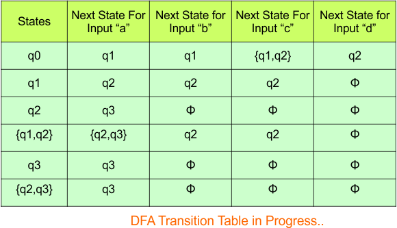
In the above DFA Table
- State Column Contains: “q0”, “q1”, “q2”, “q1q2”, “q3”, “q2q3”
- Input columns contain: “q0”, “q1”, “q2”, “q1q2”, “q3”, “q2q3”
Repeat Step 3.2: No new states exist in the DFA table, except ϕ. The transition at “ϕ” for all inputs will always remain at “ϕ”. The updated DFA table is given below.
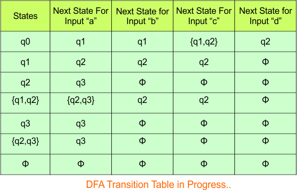
Step 3.3: At this stage, all newly generated states in the DFA table are executed successfully for their transitions, so the DFA table is ready.
Important: As “q3” was the final state in NFA Table. That’s why, all those states will be the final states where “q3” is present. Simply mark with “*” to represent the final state.
So, the following is the updated table of the DFA with its final states
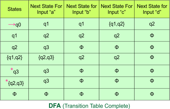
Step 4: Now draw the DFA according to the DFA Transition Table
According to the DFA transition table, we can generate the following DFA diagram.
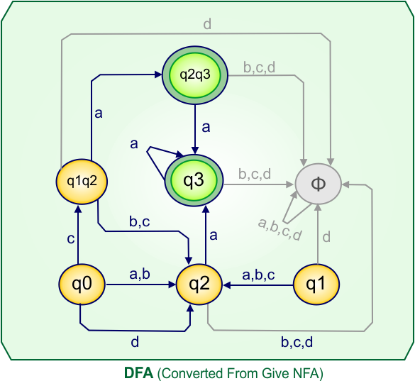
NFA to DFA Conversion Example 9.3
Step 01: Draw NFA Graph
The following is the NFA graph that needs to be converted to a DFA.
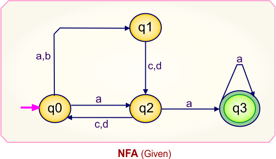
Step 02: Draw the NFA Transition Table.
The NFA transition table of the above NFA is given below
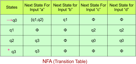
Step 03: Conversion of NFA to DFA Transition Table
Step 3.1:Select the first two rows of the NFA transition table, which will become the first two rows of the DFA transition table.
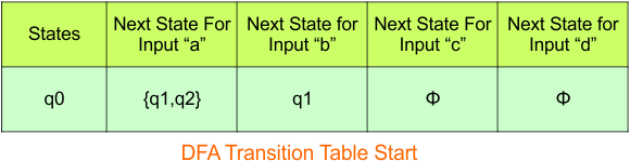
In the above DFA Table
- State Column Contains: “q0”
- Input columns contain: “q1q2”, “q1”
Step 3.2: States “q1q2” and “q1” are new states because they are present in the DFA’s input columns but do not exist in the state column. Add states “q1q2” and “q1” along with their transitions to the state column.
Transition calculations at state “q1q2”
For input “a”
δ([q1q2], a) = δ(q1, a) ∪ δ(q2, a)
= {} ∪ {q3}
= {q3}
For input “b”
δ([q1q2], b) = δ(q1, b) ∪ δ(q2, b)
= {} ∪ {}
= {}
For input “c”
δ([q1q2], c) = δ(q1, c) ∪ δ(q2, c)
= {q2} ∪ {q0}
= {q2q0}
For input “d”
δ([q1q2], d) = δ(q1, d) ∪ δ(q2, d)
= {q2} ∪ {q0}
= {q2q0}
Transition calculations at state “q1”
For input “a”
δ([q1], a) = {}
For input “b”
δ([q1], b) = {}
For input “c”
δ([q1], c) = {q2}
For input “d”
δ([q1], d) = {q2}
The updated DFA Table is given below
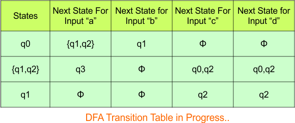
In the above DFA Table
- State Column Contains: “q0”, “q1q2”, “q1”
- Input columns contain: “q1q2”, “q1”, “q3”, “q0q2”, “q2”
Step 3.2: States “q0q2“, “q2“, and “q3” are new states because they are present in the DFA’s input columns but do not exist in the state column. Add states “q0q2“, “q2“, and “q3” along with their transitions to the state column.
Transition calculations at state “q0q2”
For input “a”
δ([q0q2], a) = δ(q0, a) ∪ δ(q2, a)
= {q1q2} ∪ {q3}
= {q1q2q3}
For input “b”
δ([q0q2], b) = δ(q0, b) ∪ δ(q2, b)
= {q1} ∪ {}
= {q1}
For input “c”
δ([q0q2], c) = δ(q0, c) ∪ δ(q2, c)
= {} ∪ {q0}
= {q0}
For input “d”
δ([q0q2], d) = δ(q0, d) ∪ δ(q2, d)
= {} ∪ {q0}
= {q0}
Transition calculations at state “q2”
For input “a”
δ([q2], a) = {q3}
For input “b”
δ([q2], b) = {}
For input “c”
δ([q2], c) = {q0}
For input “d”
δ([q2], d) = {q0}
Transition calculations at state “q3”
For input “a”
δ([q3], a) = {q3}
For input “b”
δ([q3], b) = {}
For input “c”
δ([q3], c) = {}
For input “d”
δ([q3], d) = {}
The updated DFA Table is given below
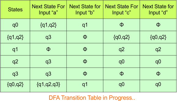
In the above DFA Table
- State Column Contains: “q0”, “q1q2”, “q1”, “q2”, “q3”, “q0q2”
- Input columns contain: “q1q2”, “q1”, “q3”, “q0q2”, “q2”, “q0”, “q1q2q3”
Repeat Step 3.2: “q1q2q3” is a new state because it is present in the input columns of the DFA but does not exist in the state column. Put “q1q2q3” in the state column along with their transitions.
Transition at state “q1q2q3”
For input “a”
δ([q1q2q3], a) = δ(q1, a) ∪ δ(q2, a) ∪ δ(q3, a)
= {} ∪ {q3} ∪ {q3}
= {q3}
For input “b”
δ([q1q2q3], b) = δ(q1, b) ∪ δ(q2, b) ∪ δ(q3, b)
= {} ∪ {} ∪ {}
= {}
For input “c”
δ([q1q2q3], c) = δ(q1, c) ∪ δ(q2, c) ∪ δ(q3, c)
= {q2} ∪ {q0} ∪ {}
= {q2q0}
For input “d”
δ([q1q2q3], d) = δ(q1, d) ∪ δ(q2, d) ∪ δ(q3, d)
= {q2} ∪ {q0} ∪ {}
= {q2q0}
Hence, the updated DFA table is given below.
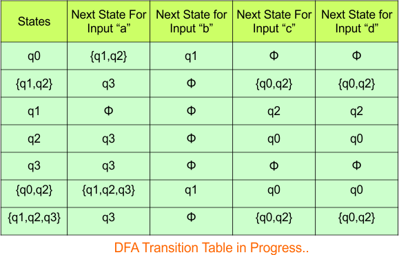
In the above DFA Table
- State Column Contains: “q0”, “q1q2”, “q1”, “q2”, “q3”, “q0q2”, “q1q2q3”
- Input columns contain: “q1q2”, “q1”, “q3”, “q0q2”, “q2”, “q0”, “q1q2q3”
Repeat Step 3.2: No new state exists in the DFA table, except ϕ. Transition at “ϕ” against all inputs will always stay at “ϕ”. The updated DFA Table is given below
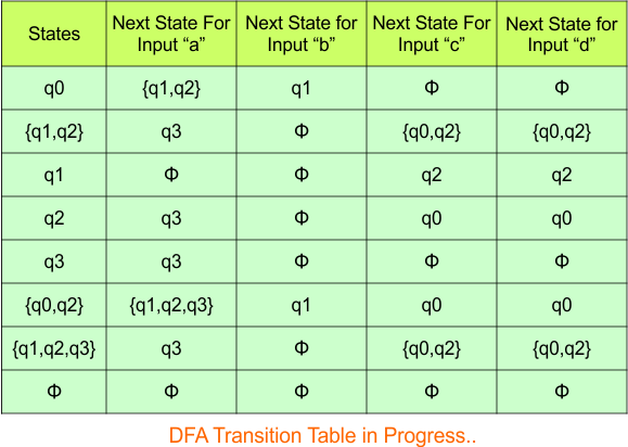
Step 3.3: At this stage, all newly generated states in the DFA table are executed successfully for their transitions, so the DFA table is ready.
Important: As “q3” was the final state in NFA Table. That’s why, all those states will be the final states where “q3” is present. Simply mark with “*” to represent the final state.
So, the following is the updated table of the DFA with its final states
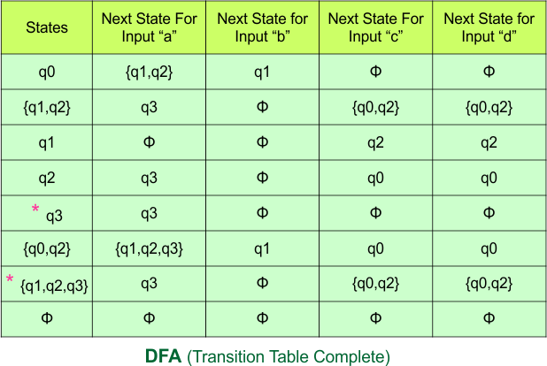
Step 4: Now draw the DFA according to the DFA Transition Table
According to the DFA transition table, we can generate the following DFA diagram.
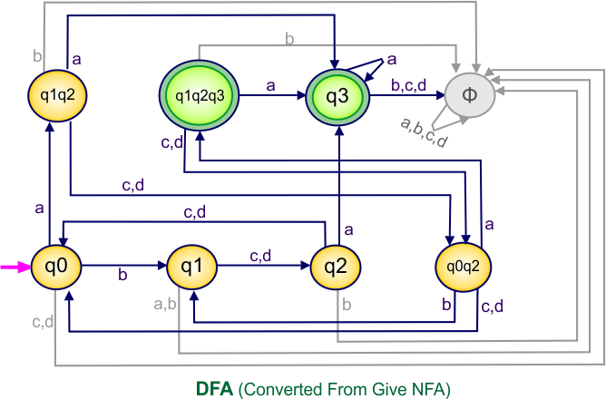
NFA to DFA Conversion Example 9.4
Step 01: Draw NFA Graph
The following is the NFA graph that needs to be converted to a DFA.
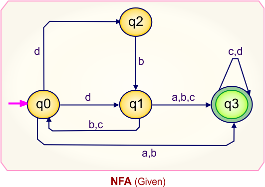
Step 02: Draw the NFA Transition Table.
The NFA transition table of the above NFA is given below
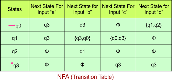
Step 03: Conversion of NFA to DFA Transition Table
Step 3.1:Select the first two rows of the NFA transition table, which will become the first two rows of the DFA transition table.

In the above DFA Table
- State Column Contains: “q0”
- Input columns contain: “q1q2”, “q3”
Step 3.2: States “q1q2” and “q3” are new states because they are present in the DFA’s input columns but do not exist in the state column. Add states “q1q2” and “q3” along with their transitions to the state column.
Transition calculations at state “q1q2”
For input “a”
δ([q1q2], a) = δ(q1, a) ∪ δ(q2, a)
= {q3} ∪ {}
= {q3}
For input “b”
δ([q1q2], b) = δ(q1, b) ∪ δ(q2, b)
= {q0q3} ∪ {q1}
= {q0q1q3}
For input “c”
δ([q1q2], c) = δ(q1, c) ∪ δ(q2, c)
= {q0q3} ∪ {}
= {q0q3}
For input “d”
δ([q1q2], d) = δ(q1, d) ∪ δ(q2, d)
= {} ∪ {}
= {}
Transition calculations at state “q3”
For input “a”
δ([q3], a) = {}
For input “b”
δ([q3], b) = {}
For input “c”
δ([q3], c) = {q3}
For input “d”
δ([q3], d) = {q3}
The updated DFA Table is given below

In the above DFA Table
- State Column Contains: “q0”, “q3”, “q1q2”
- Input columns contain: “q1q2”, “q3”, “q0q1q3”, “q0q3”
Step 3.2: States “q0q3” and “q0q1q3” are new states because they are present in the DFA’s input columns but do not exist in the state column. Add states “q0q3” and “q0q1q3” along with their transitions to the state column.
Transition calculations at state “q0q3”
For input “a”
δ([q0q3], a) = δ(q0, a) ∪ δ(q3, a)
= {q3} ∪ {}
= {q3}
For input “b”
δ([q0q3], b) = δ(q0, b) ∪ δ(q3, b)
= {q3} ∪ {}
= {q3}
For input “c”
δ([q0q3], c) = δ(q0, c) ∪ δ(q3, c)
= {} ∪ {q3}
= {q3}
For input “d”
δ([q0q3], d) = δ(q0, d) ∪ δ(q3, d)
= {q1q2} ∪ {q3}
= {q1q2q3}
ransition calculations at state “q0q1q3”
For input “a”
δ([q0q1q3], a) = δ(q0, a) ∪ δ(q1, a) ∪ δ(q3, a)
= {q3} ∪ {q3} ∪ {}
= {q3}
For input “b”
δ([q0q1q3], b) = δ(q0, b) ∪ δ(q1, b) ∪ δ(q3, b)
= {q3} ∪ {q0q3} ∪ {}
= {q0q3}
For input “c”
δ([q0q1q3], c) = δ(q0, c) ∪ δ(q1, c) ∪ δ(q3, c)
= {} ∪ {q0q3} ∪ {q3}
= {q0q3}
For input “d”
δ([q0q1q3], d) = δ(q0, d) ∪ δ(q1, d) ∪ δ(q3, d)
= {q1q2} ∪ {} ∪ {q3}
= {q1q2q3}
The updated DFA Table is given below

In the above DFA Table
- State Column Contains: “q0”, “q3”, “q1q2”, “q0q1q3”, “q0q3”
- Input columns contain: “q0”, “q3”, “q1q2”, “q0q1q3”, “q0q3”, “q1q2q3”
Repeat Step 3.2: “q1q2q3” is a new state because it is present in the input columns of the DFA but does not exist in the state column. Put “q1q2q3” in the state column along with their transitions.
Transition at state “q1q2q3”
For input “a”
δ([q1q2q3], a) = δ(q1, a) ∪ δ(q2, a) ∪ δ(q3, a)
= {q3} ∪ {} ∪ {}
= {q3}
For input “b”
δ([q1q2q3], b) = δ(q1, b) ∪ δ(q2, b) ∪ δ(q3, b)
= {q0q3} ∪ {q1} ∪ {}
= {q0q1q3}
For input “c”
δ([q1q2q3], c) = δ(q1, c) ∪ δ(q2, c) ∪ δ(q3, c)
= {q0q3} ∪ {} ∪ {q3}
= {q0q3}
For input “d”
δ([q1q2q3], d) = δ(q1, d) ∪ δ(q2, d) ∪ δ(q3, d)
= {} ∪ {} ∪ {q3}
= {q3}
Hence, the updated DFA table is given below.

In the above DFA Table
- State Column Contains: “q0”, “q3”, “q1q2”, “q0q1q3”, “q0q3”, “q1q2q3”
- Input columns contain: “q0”, “q3”, “q1q2”, “q0q1q3”, “q0q3”, “q1q2q3”
Repeat Step 3.2: No new state exists in the DFA table, except ϕ. Transition at “ϕ” against all inputs will always stay at “ϕ”. The updated DFA Table is given below

Step 3.3: At this stage, all newly generated states in the DFA table are executed successfully for their transitions, so the DFA table is ready.
Important: As “q3” was the final state in NFA Table. That’s why, all those states will be the final states where “q3” is present. Simply mark with “*” to represent the final state.
So, the following is the updated table of the DFA with its final states
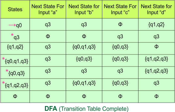
Step 4: Now draw the DFA according to the DFA Transition Table
According to the DFA transition table, we can generate the following DFA diagram
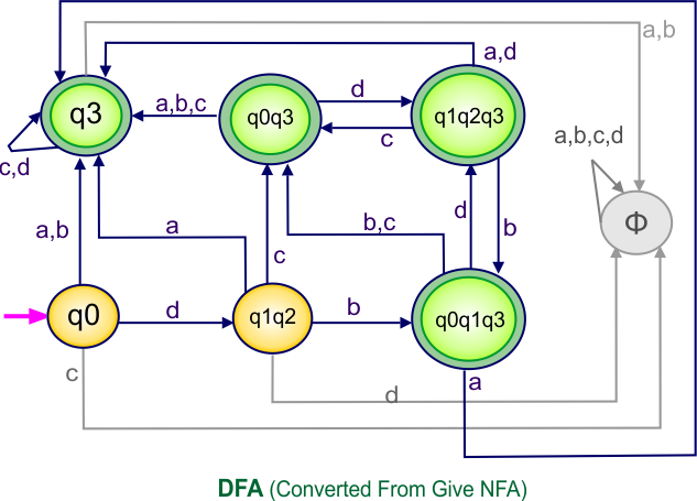
NFA to DFA Category-10 Examples: 5-States, 2-Input Symbols
Category 10 covers NFA to DFA conversions for machines with five states over the two input alphabets {a,b} or {0,1}.
NFA to DFA Conversion Example 10.1
Step 01: Draw NFA Graph
The following is the NFA graph that needs to be converted to a DFA.
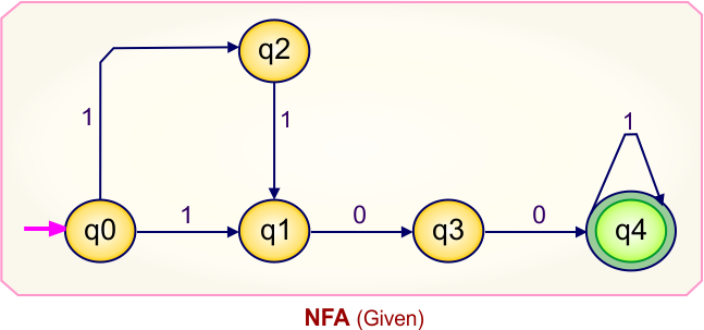
Step 02: Draw the NFA transition Table.
The NFA transition table of the above NFA is given below
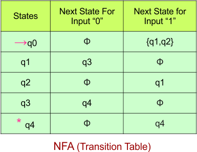
Step 03: Conversion of NFA to DFA Transition Table
Let’s start the conversion of the NFA transition table to the DFA transition Table.
Step 3.1: Select the first two rows of the NFA transition table, which will become the first two rows of the DFA transition table given below.

In the above DFA Table
- State Column Contains: “q0”
- Input columns contain: “q0q2″
Step 3.2: State “q1q2” are new states because it is present in the input columns of the DFA but do not exist in the state column. Put “q1q2” in the state column along with their transitions.
Transition at state “q1q2” against
For input “0”
δ([q1q2], 0) = δ(q1, 0) ∪ δ(q2, 0)
= {q3} ∪ {ϕ}
= {q3}
For input “1”
δ([q1q2], 1) = δ(q1, 1) ∪ δ(q2, 1)
= {ϕ} ∪ {q1}
= {q1}
Hence, the updated DFA table is given below

Repeat Step 3.2: State “q0” and “q1q2” exist in the state column of the DFA. However, the states “q3” and “q1” do not appear in the state column. Therefore, we should simply add these states to the state column.
The transitions for “q3” are given below
For input “0”
δ([q3], 0) = {q4}
For input “1”
δ([q3], 1) = {ϕ}
The transitions for “q1” are given below
For input “0”
δ([q1], 0) = {q3}
For input “1”
δ([q1], 1) = {ϕ}
The Update DFA Table is given below

Repeat Step 3.2: State “q4” exist in the state column of the DFA. However, the states “q4” occur in the DFA table but do not appear in the state column. Therefore, we should simply add this state to the state column
The transitions for “q4” are given below
For input “0”
δ([q4], 0) = {ϕ}
For input “1”
δ([q4], 1) = {q4}
The Update DFA Table is given below

Repeat Step 3.2: States”q0″, “q1q2“, “q3”, “q1”, and “q4” exist in the state column of the DFA. No new state exists in the DFA table, except ϕ. Transition at “ϕ” against both inputs “0” and “1” is given below,
For input “0”
δ([ϕ], 0) = {ϕ}
For input “1”
δ([ϕ], 1) = {ϕ}
The updated DFA Table is given below,

Step 3.3: At this stage, all newly generated states in the DFA table are executed successfully for their transitions, so the DFA table is ready.
Important: As q4 was the final state in NFA Table. That’s why, all those states will be the final states where q4 is present. Simply mark with “*” to represent the final state.
So, the following is the updated table of the DFA with its final states
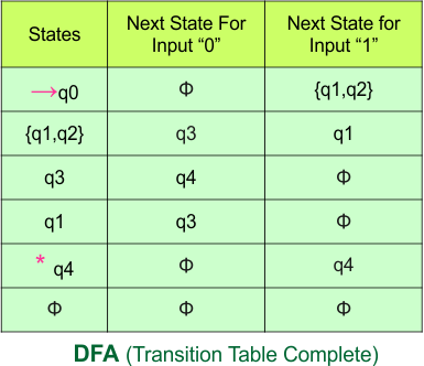
Step 4: Now draw the DFA according to the DFA Transition Table
According to the DFA transition table, we can generate the following DFA diagram.
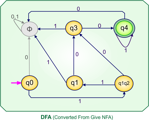
NFA to DFA Conversion Example 10.2
Step 01: Draw NFA Graph
The following is the NFA graph that needs to be converted to a DFA.
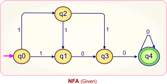
Step 02: Draw the NFA transition Table.
The NFA transition table of the above NFA is given below

Step 03: Conversion of NFA to DFA Transition Table
Let’s start the conversion of the NFA transition table to the DFA transition Table.
Step 3.1: Select the first two rows of the NFA transition table, which will become the first two rows of the DFA transition table given below.
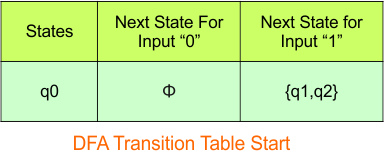
In the above DFA Table
- State Column Contains: “q0”
- Input columns contain: “q0q2″
Step 3.2: State “q1q2” is are new state because it is present in the input columns of the DFA but does not exist in the state column. Put “q1q2” in the state column along with their transitions.
Transition at state “q1q2” against
For input “0”
δ([q1q2], 0) = δ(q1, 0) ∪ δ(q2, 0)
= {q3} ∪ {ϕ}
= {q3}
For input “1”
δ([q1q2], 1) = δ(q1, 1) ∪ δ(q2, 1)
= {ϕ} ∪ {q1q3}
= {q1q3}
Hence, the updated DFA table is given below
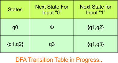
Repeat Step 3.2: State “q0” and “q1q2” exist in the state column of the DFA. However, the state “q1q3” does not appear in the state column. Therefore, we should simply add these states to the state column.
Transition at state “q1q3” against
For input “0”
δ([q1q3], 0) = δ(q1, 0) ∪ δ(q3, 0)
= {q3} ∪ {q4}
= {q3q4}
For input “1”
δ([q1q3], 1) = δ(q1, 1) ∪ δ(q3, 1)
= {ϕ} ∪ {ϕ}
= {ϕ}
Hence, the updated DFA table is given below
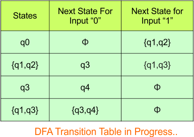
Step 3.2: State “q3q4” and “q4” are new states because it is present in the input columns of the DFA but do not exist in the state column. Put “q3q4” and “q4” in the state column along with their transitions.
Transition at state “q3q4” against
For input “0”
δ([q3q4], 0) = δ(q3, 0) ∪ δ(q4, 0)
= {q4} ∪ {q4}
= {q4}
For input “1”
δ([q3q4], 1) = δ(q3, 1) ∪ δ(q4, 1)
= {ϕ} ∪ {ϕ}
= {ϕ}
The transitions for “q4” are given below
For input “0”
δ([q4], 0) = {q4}
For input “1”
δ([q4], 1) = {ϕ}
The Update DFA Table is given below
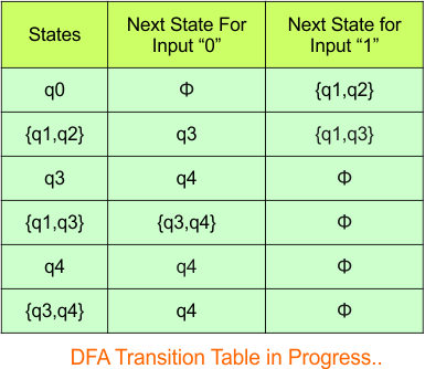
Repeat Step 3.2: No new state exists in the DFA table, except ϕ. Transition at “ϕ” against both inputs “0” and “1” is given below,
For input “0”
δ([ϕ], 0) = {ϕ}
For input “1”
δ([ϕ], 1) = {ϕ}
The updated DFA Table is given below,
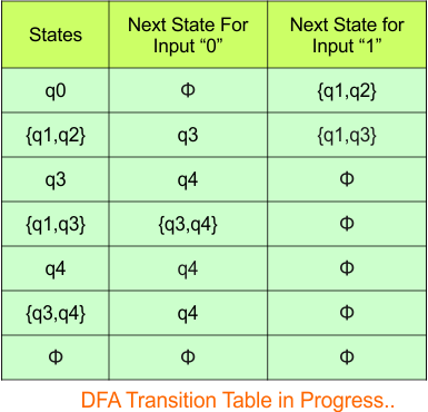
Step 3.3: At this stage, all newly generated states in the DFA table are executed successfully for their transitions, so the DFA table is ready.
Important: As q4 was the final state in NFA Table. That’s why, all those states will be the final states where q4 is present. Simply mark with “*” to represent the final state.
So, the following is the updated table of the DFA with its final states

Step 4: Now draw the DFA according to the DFA Transition Table
According to the DFA transition table, we can generate the following DFA diagram.
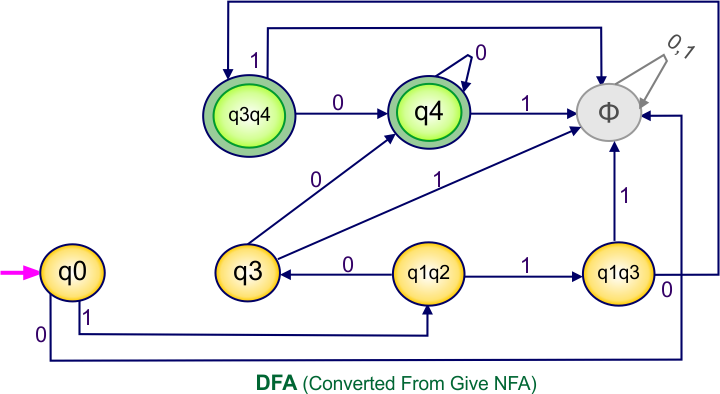
NFA to DFA Conversion Example 10.3
Step 01: Draw NFA Graph
The following is the NFA graph that needs to be converted to a DFA.
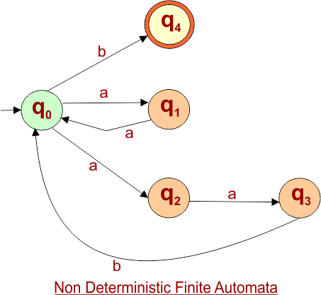
Step 02: NFA Transition Table
The NFA transition table of the above NFA Diagram is given below
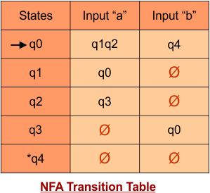
Don’t confuse: Fi(“ϕ”) symbol represents the empty symbol (or “-“).
Step 03: Conversion of NFA to DFA Transition Table
Let’s start the conversion of the NFA transition table to the DFA transition Table.
Step 3.1: Select the first two rows of the NFA transition table, which will become the first two rows of the DFA transition table given below.
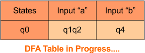
In the above DFA Table
- State Column Contains: “q0”
- Input columns contain: “q1q2”, “q4”
Step 3.2: State “q1q2” and “q4” are new states because it is present in the input columns of the DFA but do not exist in the state column. Put “q1q2” and “q4” in the state column along with their transitions.
State “q1q2” Transition
For input “a”
δ([q1q2], a) = δ(q1, a) ∪ δ(q2, a)
= {q0} ∪ {q3}
= {q0q3}
For input “b”
δ([q1q2], b) = δ(q1, b) ∪ δ(q2, b)
= {ϕ} ∪ {ϕ}
= {ϕ}
State “q4 ” Transitions
For input “a”
δ([q4], a) = {ϕ}
For input “b”
δ([q4], b) = {ϕ}
Put the newly generated states (“q1q2″ and “q4”) and their transitions in the DFA Table. The updated DFA Table is given below
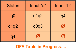
In the above DFA Table
- State Column Contains: “q0”, “q1q2”, “q4”
- Input columns contain: “q1q2”, “q4”, “q0q3”, “qϕ“
Repeat Step 3.2: “q0q3” is a new state because it is present in the input columns of the DFA but does not exist in the state column. Put “q0q3” in the state column along with its transitions.
Transition calculations for state “q0q3”
For input “a”
δ([q0q3], a) = δ(q0, a) ∪ δ(q3, a)
= {q1q2} ∪ {ϕ}
= {q1q2}
For input “b”
δ([q0q3], b) = δ(q0, b) ∪ δ(q3, b)
= {q4} ∪ {q0}
= {q4q0}
Put transitions in the DFA Table. The updated DFA Table is given below
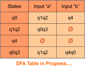
In the above DFA Table
- State Column Contains: “q0”, “q1q2”, “q4”, “q0q3”
- Input columns contain: “q1q2”, “q4”, “q0q3”, “qϕ“, “q4q0”
Repeat Step 3.2: “q4q0” is a new state because it is present in the input columns of the DFA but does not exist in the state column. Put “q4q0” in the state column along with its transitions.
Transition calculations for state “q4q0”
For input “a”
δ([q4q0], a) = δ(q4, a) ∪ δ(q0, a)
= {ϕ} ∪ {q1q2}
= {q1q2}
For input “b”
δ([q4q0], b) = δ(q4, b) ∪ δ(q0, b)
= {ϕ} ∪ {q4}
= {q4}
Put transitions in the DFA Table. The updated DFA Table is given below
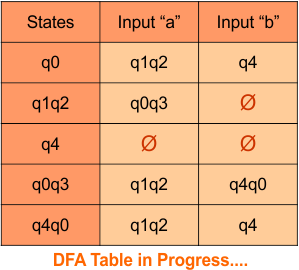
In the above DFA Table
- State Column Contains: “q0”, “q1q2”, “q4”, “q0q3”, “q4q0”
- Input columns contain: “q1q2”, “q4”, “q0q3”, “qϕ“, “q4q0”
Repeat Step 3.2: “qϕ” is a new state because it is present in the input columns of the DFA but does not exist in the state column. Put “qϕ” in the state column along with its transitions.
Transition calculations for state “qϕ”
For input “a”
δ([ϕ], a) = {ϕ}
For input “b”
δ([ϕ], b) = {ϕ}
Put transitions in the DFA Table. The updated DFA Table is given below
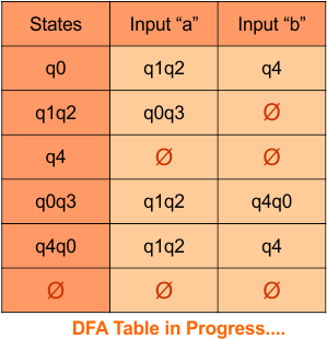
In the above DFA Table
- State Column Contains: “q0”, “q1q2”, “q4”, “q0q3”, “q4q0”, “qϕ“
- Input columns contain: “q1q2”, “q4”, “q0q3”, “qϕ“, “q4q0”
At this stage, no new state remains. The DFA table is one step away to complete.
Step 3.3: State “q4” was the final state in the NFA Table. That’s why all those states will be the final states where “q4” is present in the DFA state column. Simply mark with “*” to represent the final state.
Here is the complete DFA transition table with its final states
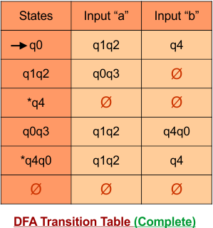
Step 4: Now draw the DFA according to the DFA transition table
According to the DFA transition table, we can generate the following DFA diagram.
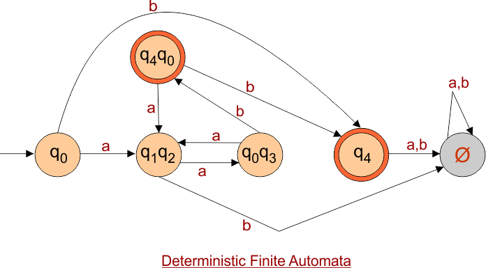
NFA to DFA Conversion Example 10.4
Step 01: Draw NFA Graph
The following is the NFA graph that needs to be converted to a DFA.
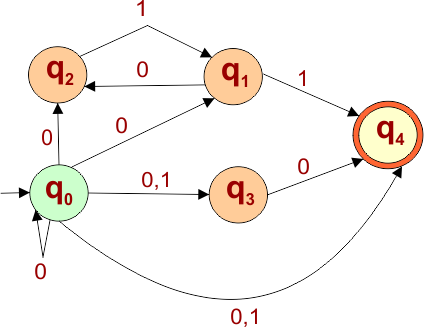
Step 02: Draw the NFA transition Table.
The NFA transition table of the above NFA is given below
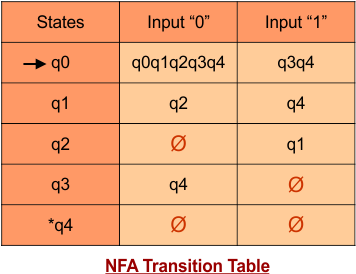
Step 03: Conversion of NFA to DFA Transition Table
Let’s start the conversion of the NFA transition table to the DFA transition Table.
Step 3.1: Select the first two rows of the NFA transition table, which will become the first two rows of the DFA transition table given below.
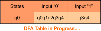
In the above DFA Table
- State Column Contains: “q0”
- Input columns contain: “q0q1q2q3q4“, “q3q4”
Step 3.2: State “q0q1q2q3q4” and “q3q4” are new states because it is present in the input columns of the DFA but do not exist in the state column. Put “q0q1q2q3q4” and “q3q4” in the state column along with their transitions.
Transition calculations for state “q0q1q2q3q4”
For input “0”
δ([q0q1q2q3q4], 0) = δ(q0, 0) ∪ δ(q1, 0) ∪ δ(q2, 0) ∪ δ(q3, 0) ∪ δ(q4, 0)
= {q0q1q2q3q4} ∪ {q2} ∪ {ϕ} ∪ {q4} ∪ {ϕ}
= {q0q1q2q3q4}
For input “1”
δ([q0q1q2q3q4], 1) = δ(q0, 1) ∪ δ(q1, 1) ∪ δ(q2, 1) ∪ δ(q3, 1) ∪ δ(q4, 1)
= {q3q4} ∪ {q4} ∪ {q1} ∪ {ϕ} ∪ {ϕ}
= {q1q3q4}
Transition at state “q3q4” against
For input “0”
δ([q3q4], 0) = δ(q3, 0) ∪ δ(q4, 0)
= {q4} ∪ {ϕ}
= {q4}
For input “1”
δ([q3q4], 1) = δ(q3, 1) ∪ δ(q4, 1)
= {ϕ} ∪ {ϕ}
= {ϕ}
Hence, the updated DFA table is given below, where
- The Transition of “q0q1q2q3q4” against input “0” is “q0q1q2q3q4“, and the transition against input “1” is “q1q3q4“.
- The Transition of “q3q4” against input “0” is “q4“, and the transition against input “1” is “ϕ“.
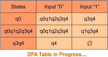
Repeat Step 3.2: State “q0”, “q0q1q2q3q4“, and “q3q4” exist in the state column of the DFA. However, the states “q1q3q4” and “q4” occur in the DFA table but do not appear in the state column. Therefore, we should simply add these states to the state column.
Transition at state “q1q3q4”
For input “0”
δ([q1q3q4], 0) = δ(q1, 0) ∪ δ(q3, 0) ∪ δ(q4, 0)
= {q2} ∪ {q4} ∪ {ϕ}
= {q2q4}
For input “1”
δ([q1q3q4], 1) = δ(q1, 1) ∪ δ(q3, 1) ∪ δ(q4, 1)
= {q4} ∪ {ϕ} ∪ {ϕ}
= {q4}
The transitions for “q4” are given below
For input “0”
δ([q4], 0) = {ϕ}
For input “1”
δ([q4], 1) = {ϕ}
The Update DFA Table is given below
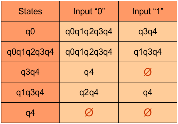
Repeat Step 3.2: State “q0”, “q0q1q2q3q4“, “q3q4”, “q1q3q4”, and “q4” exist in the state column of the DFA. However, the states “q2q4” occur in the DFA table but do not appear in the state column. Therefore, we should simply add these states to the state column.
Transition at state “q2q4”
For input “0”
δ([q2q4], 0) = δ(q2, 0) ∪ δ(q4, 0)
= {ϕ} ∪ {ϕ}
= {ϕ}
For input “1”
δ([q2q4], 1) = δ(q2, 1) ∪ δ(q4, 1)
= {q1} ∪ {ϕ}
= {q1}
The Update DFA Table is given below
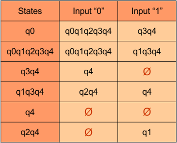
Repeat Step 3.2: States”q0″, “q0q1q2q3q4“, “q3q4”, “q1q3q4”, “q4”, and “q2q4” exist in the state column of the DFA. However, the states “q1” occur in the DFA table but does not appear in the state column. Therefore, we should simply add these states to the state column.
Transition at state “q1”
For input “0”
δ([q1], 0) = {q2}
For input “1”
δ([q1], 1) = {q4}
The Update DFA Table is given below
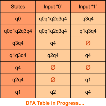
Repeat Step 3.2: States”q0″, “q0q1q2q3q4“, “q3q4”, “q1q3q4”, “q4”, “q2q4”, and “q1” exist in the state column of the DFA. However, the state “q2” occurs in the DFA table but does not appear in the state column. Therefore, we should simply add these states to the state column.
Transition at state “q2”
For input “0”
δ([q2], 0) = {ϕ}
For input “1”
δ([q2], 1) = {q1}
The Update DFA Table is given below
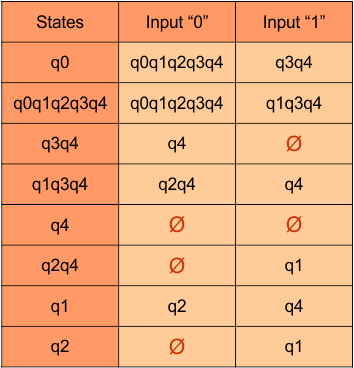
Repeat Step 3.2: States”q0″, “q0q1q2q3q4“, “q3q4”, “q1q3q4”, “q4”, “q2q4”, “q1”, and “q2” exist in the state column of the DFA. No new state exists in the DFA table, except ϕ. Transition at “ϕ” against both inputs “0” and “1” is given below
For input “0”
δ([ϕ], 0) = {ϕ}
For input “1”
δ([ϕ], 1) = {ϕ}
The Update DFA Table is given below
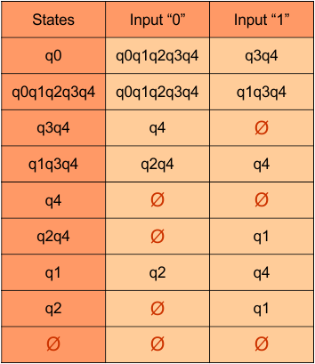
Step 3.3: At this stage, all newly generated states in the DFA table are executed successfully for their transitions, so the DFA table is ready.
Important: As q4 was the final state in NFA Table. That’s why, all those states will be the final states where q4 is present. Simply mark with “*” to represent the final state.
So, the following is the updated table of the DFA with its final states
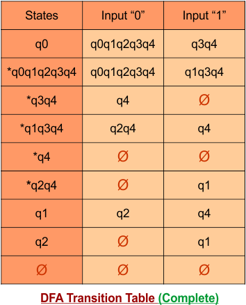
Step 4: Now draw the DFA according to the DFA Transition Table
According to the DFA transition table, we can generate the following DFA diagram.
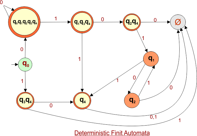
NFA to DFA Conversion Example 10.5
Step 01: Draw NFA Graph
The following is the NFA graph that needs to be converted to a DFA.
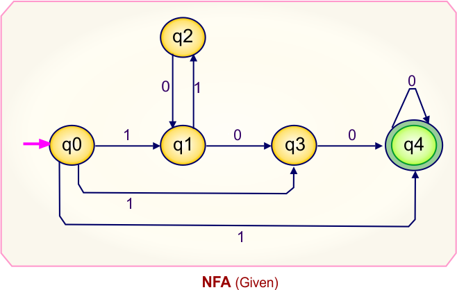
Step 02: Draw the NFA transition Table.
The NFA transition table of the above NFA is given below

Step 03: Conversion of NFA to DFA Transition Table
Let’s start the conversion of the NFA transition table to the DFA transition Table.
Step 3.1: Select the first two rows of the NFA transition table, which will become the first two rows of the DFA transition table given below.
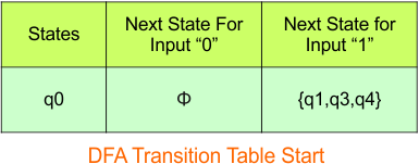
In the above DFA Table
- State Column Contains: “q0”
- Input columns contain: “q1q3q4″
Step 3.2: State “q1q3q4” is are new state because it is present in the input columns of the DFA but does not exist in the state column. Put “q1q2” in the state column along with their transitions.
Transition at state “q1q3q4” against
For input “0”
δ([q1q3q4], 0) = δ(q1, 0) ∪ δ(q3, 0) ∪ δ(q4, 0)
= {q3} ∪ {q4} ∪ {q4}
= {q3q4}
For input “1”
δ([q1q3q4], 1) = δ(q1, 1) ∪ δ(q3, 1) ∪ δ(q4, 1)
= {q2} ∪ {ϕ} ∪ {ϕ}
= {q2}
Hence, the updated DFA table is given below
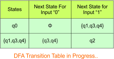
Repeat Step 3.2: State “q0” and “q1q3q4” exist in the state column of the DFA. However, the states “q3q4” and “q2” do not appear in the state column. Therefore, we should simply add these states to the state column.
Transition at state “q3q4” against
For input “0”
δ([q3q4], 0) = δ(q3, 0) ∪ δ(q4, 0)
= {q4} ∪ {q4}
= {q4}
For input “1”
δ([q3q4], 1) = δ(q3, 1) ∪ δ(q4, 1)
= {ϕ} ∪ {ϕ}
= {ϕ}
The transitions for “q2” are given below
For input “0”
δ([q2], 0) = {q1}
For input “1”
δ([q2], 1) = {ϕ}
Hence, the updated DFA table is given below
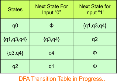
Repeat Step 3.2: State “q0”, “q3q4″,”q2” and “q1q3q4” exist in the state column of the DFA. However, the states “q1” and “q4” do not appear in the state column. Therefore, we should simply add these states to the state column.
The transitions for “q1” are given below
For input “0”
δ([q1], 0) = {q3}
For input “1”
δ([q1], 1) = {q2}
The transitions for “q4” are given below
For input “0”
δ([q4], 0) = {q4}
For input “1”
δ([q4], 1) = {ϕ}
The Update DFA Table is given below
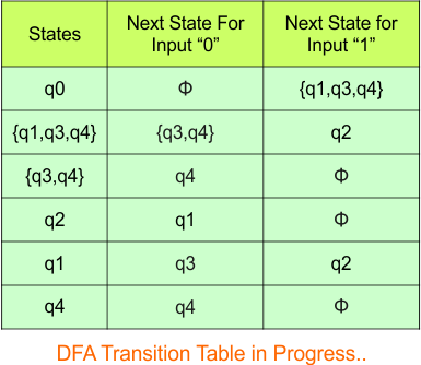
Repeat Step 3.2: State “q0”, “q3q4”, “q2”, and “q1q3q4” exist in the state column of the DFA. However, the states “q1” and “q4” do not appear in the state column. Therefore, we should simply add these states to the state column.
The transitions for “q3” are given below
For input “0”
δ([q3], 0) = {q4}
For input “1”
δ([q3], 1) = {ϕ}
The updated DFA Table is given below
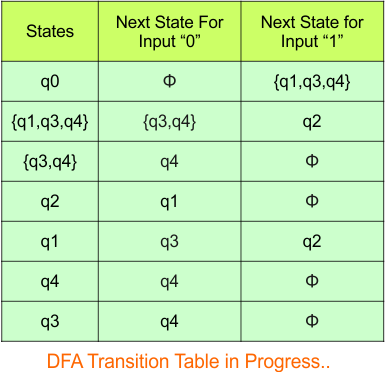
Repeat Step 3.2: No new state exists in the DFA table, except ϕ. Transition at “ϕ” against both inputs “0” and “1” is given below,
For input “0”
δ([ϕ], 0) = {ϕ}
For input “1”
δ([ϕ], 1) = {ϕ}
The updated DFA Table is given below,
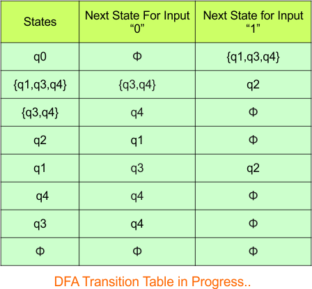
Step 3.3: At this stage, all newly generated states in the DFA table are executed successfully for their transitions, so the DFA table is ready.
Important: As q4 was the final state in NFA Table. That’s why, all those states will be the final states where q4 is present. Simply mark with “*” to represent the final state.
So, the following is the updated table of the DFA with its final states

Step 4: Now draw the DFA according to the DFA Transition Table
According to the DFA transition table, we can generate the following DFA diagram.
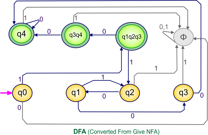
NFA to DFA Conversion Example 10.6
Step 01: Draw NFA Graph
The following is the NFA graph that needs to be converted to a DFA.
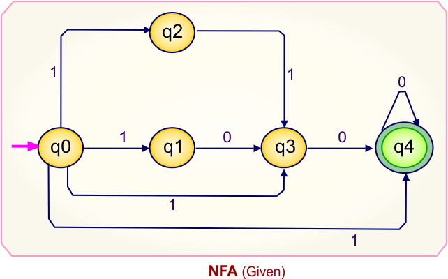
Step 02: Draw the NFA transition Table.
The NFA transition table of the above NFA is given below

Step 03: Conversion of NFA to DFA Transition Table
Let’s start the conversion of the NFA transition table to the DFA transition Table.
Step 3.1: Select the first two rows of the NFA transition table, which will become the first two rows of the DFA transition table given below.
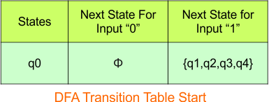
In the above DFA Table
- State Column Contains: “q0”
- Input columns contain: “q1q2q3q4″
Step 3.2: State “q1q2q3q4” is are new state because it is present in the input columns of the DFA but does not exist in the state column. Put “q1q2” in the state column along with their transitions.
Transition at state “q1q2q3q4” against
For input “0”
δ([q1q2q3q4], 0) = δ(q1, 0) ∪ δ(q2, 0) ∪ δ(q3, 0) ∪ δ(q4, 0)
= {q3} ∪ {ϕ} ∪ {q4} ∪ {q4}
= {q3q4}
For input “1”
δ([q1q2q3q4], 1) = δ(q1, 1) ∪ δ(q2, 1) ∪ δ(q3, 1) ∪ δ(q4, 1)
= {ϕ} ∪ {q3} ∪ {ϕ} ∪ {ϕ}
= {q3}
Hence, the updated DFA table is given below
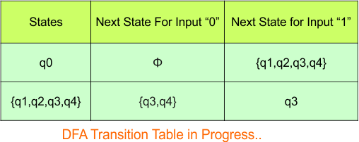
Repeat Step 3.2: State “q0” and “q1q2q3q4” exist in the state column of the DFA. However, the states “q3q4” and “q3” do not appear in the state column. Therefore, we should simply add these states to the state column.
Transition at state “q3q4” against
For input “0”
δ([q3q4], 0) = δ(q3, 0) ∪ δ(q4, 0)
= {q4} ∪ {q4}
= {q4}
For input “1”
δ([q3q4], 1) = δ(q3, 1) ∪ δ(q4, 1)
= {ϕ} ∪ {ϕ}
= {ϕ}
The transitions for “q3” are given below
For input “0”
δ([q3], 0) = {q4}
For input “1”
δ([q3], 1) = {ϕ}
Hence, the updated DFA table is given below
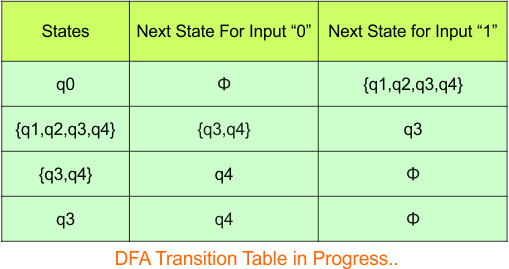
Repeat Step 3.2: State “q0”, “q3q4″,”q3” and “q1q2q3q4” exist in the state column of the DFA. However, the state “q4” do not appear in the state column. Therefore, we should simply add this state to the state column.
The transitions for “q4” are given below
For input “0”
δ([q4], 0) = {q4}
For input “1”
δ([q4], 1) = {ϕ}
The updated DFA Table is given below
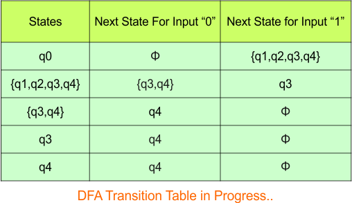
Repeat Step 3.2: No new state exists in the DFA table, except ϕ. Transition at “ϕ” against both inputs “0” and “1” is given below,
For input “0”
δ([ϕ], 0) = {ϕ}
For input “1”
δ([ϕ], 1) = {ϕ}
The updated DFA Table is given below,
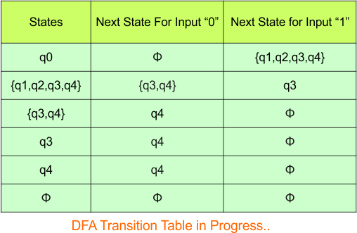
Step 3.3: At this stage, all newly generated states in the DFA table are executed successfully for their transitions, so the DFA table is ready.
Important: As q4 was the final state in NFA Table. That’s why, all those states will be the final states where q4 is present. Simply mark with “*” to represent the final state.
So, the following is the updated table of the DFA with its final states

Step 4: Now draw the DFA according to the DFA Transition Table
According to the DFA transition table, we can generate the following DFA diagram.
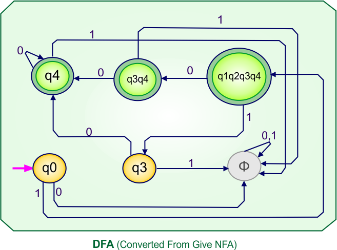
NFA to DFA Category-11 Examples: 5-States, 3-Input Symbols
Category 11 covers NFA to DFA conversions for machines with five states over the three input alphabets {a,b,c}.
NFA to DFA Conversion Example 11.1
Step 01: Draw NFA Graph
The following is the NFA graph that needs to be converted to a DFA.
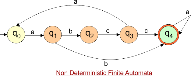
Step 02: Draw the NFA Transition Table.
The NFA transition table of the above NFA is given below
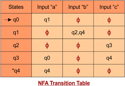
Step 03: Conversion of NFA to DFA Transition Table
Step 3.1:Select the first two rows of the NFA transition table, which will become the first two rows of the DFA transition table.
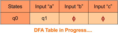
Step 3.2: Only “q0” exists in the state column of the DFA. However, the state “q1” occurs in the DFA table but does not appear in the state column. Therefore, we should simply add this state to the state column. The transitions for “q1” are given below
Transition at state “q1” against all inputs “a”, “b”, and “c”
For input “a”
δ([q1], a) = {ϕ}
For input “b”
δ([q1], b) = {q2q4}
For input “c”
δ([q1], c) = {ϕ}
The updated DFA Table is given below
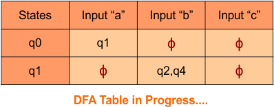
Repeat Step 3.2: State “q0” and “q1” exist in the state column of the DFA. However, the state “q2q4” occurs in the DFA table but does not appear in the state column. Therefore, we should add these states to the state column.
Transition at state “q2q4” against all inputs “a”, “b”, and “c”
For input “a”
δ([q2q4], a) = δ(q2, a) ∪ δ(q4, a)
= {ϕ} ∪ {q4}
= {q4}
For input “b”
δ([q2q4], b) = δ(q2, b) ∪ δ(q4, b)
= {ϕ} ∪ {ϕ}
= {ϕ}
For input “c”
δ([q2q4], c) = δ(q2, c) ∪ δ(q4, c)
= {q3} ∪ {ϕ}
= {q3}
The updated DFA Table is given below
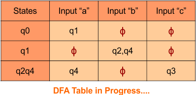
Repeat Step 3.2: State “q0”, “q1“, and “q2q4” exist in the state column of the DFA. However, the states “q3” and “q4” occur in the DFA table but do not appear in the state column. Therefore, we should add these states to the state column.
Transition at state “q3” against all inputs “a”, “b”, and “c”
For input “a”
δ([q3], a) = {q0}
For input “b”
δ([q3], b) = {ϕ}
For input “c”
δ([q3], c) = {q4}
Transition at state “q4” against all inputs “a”, “b”, and “c”
For input “a”
δ([q4], a) = {q4}
For input “b”
δ([q4], b) = {ϕ}
For input “c”
δ([q4], c) = {ϕ}
The updated DFA Table is given below
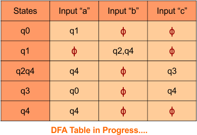
Step 3.3: At this stage, all newly generated states in the DFA table are executed successfully for their transitions, so the DFA table is ready.
Important: As q4 was the final state in NFA Table. That’s why, all those states will be the final states where q4 is present. Simply mark with “*” to represent the final state.
So, the following is the updated table of the DFA with its final states
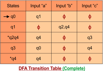
Step 4: Now draw the DFA according to the DFA Transition Table
According to the DFA transition table, we can generate the following DFA diagram.
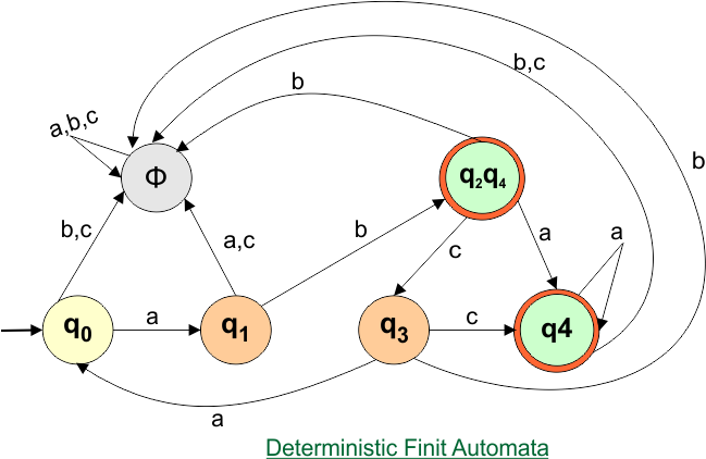
NFA to DFA Conversion Example 11.2
Step 01: Draw NFA Graph
The following is the NFA graph that needs to be converted to a DFA.
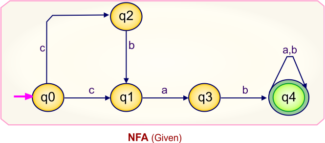
Step 02: Draw the NFA Transition Table.
The NFA transition table of the above NFA is given below
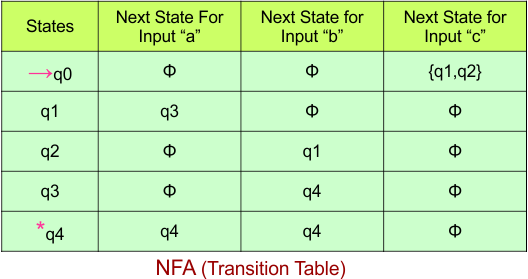
Step 03: Conversion of NFA to DFA Transition Table
Step 3.1:Select the first two rows of the NFA transition table, which will become the first two rows of the DFA transition table.

Step 3.2: Only “q0” exists in the state column of the DFA. However, the state “q1q2” occurs in the DFA table but does not appear in the state column. Therefore, we should simply add this state to the state column. The transitions for “q1” are given below
Transition at state “q1q2” against all inputs “a”, “b”, and “c”
For input “a”
δ([q1q2], a) = δ(q1, a) ∪ δ(q2, a)
= {q3} ∪ {ϕ}
= {q3}
For input “b”
δ([q1q2], b) = δ(q1, b) ∪ δ(q2, b)
= {ϕ} ∪ {q1}
= {q1}
For input “c”
δ([q1q2], c) = δ(q1, c) ∪ δ(q2, c)
= {ϕ} ∪ {ϕ}
= {ϕ}
The updated DFA Table is given below

Repeat Step 3.2: State “q0” and “q1q2” exist in the state column of the DFA. However, the state “q1” and “q3” occurs in the DFA table but does not appear in the state column. Therefore, we should add these states to the state column.
Transition at state “q1” against all inputs “a”, “b”, and “c”
For input “a”
δ([q1], a) = {q3}
For input “b”
δ([q1], b) = {ϕ}
For input “c”
δ([q1], c) = {ϕ}
Transition at state “q3” against all inputs “a”, “b”, and “c”
For input “a”
δ([q3], a) = {ϕ}
For input “b”
δ([q3], b) = {q4}
For input “c”
δ([q3], c) = {ϕ}
The updated DFA Table is given below

Repeat Step 3.2: State “q0”, “q1,q2“, “q1” and “q3” exist in the state column of the DFA. However, the state “q4” occur in the DFA table but do not appear in the state column. Therefore, we should add these states to the state column.
Transition at state “q4” against all inputs “a”, “b”, and “c”
For input “a”
δ([q4], a) = {q4}
For input “b”
δ([q4], b) = {q4}
For input “c”
δ([q4], c) = {ϕ}
The updated DFA Table is given below

Repeat Step 3.2: No new state exists in the DFA table, except ϕ. Transition at “ϕ” against all inputs will always stay at “ϕ”. The updated DFA Table is given below

Step 3.3: At this stage, all newly generated states in the DFA table are executed successfully for their transitions, so the DFA table is ready.
Important: As q4 was the final state in NFA Table. That’s why, all those states will be the final states where q4 is present. Simply mark with “*” to represent the final state.
So, the following is the updated table of the DFA with its final states
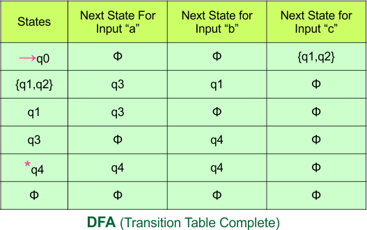
Step 4: Now draw the DFA according to the DFA Transition Table
According to the DFA transition table, we can generate the following DFA diagram
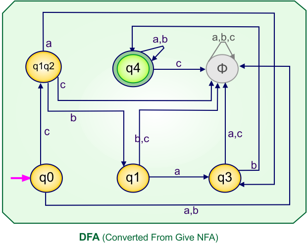
NFA to DFA Conversion Example 11.3
Step 01: Draw NFA Graph
The following is the NFA graph that needs to be converted to a DFA.
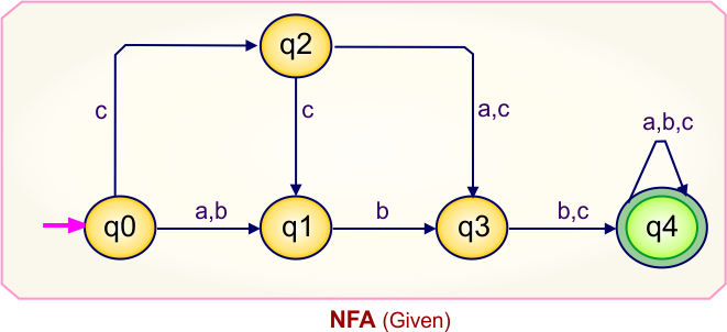
Step 02: Draw the NFA Transition Table.
The NFA transition table of the above NFA is given below

Step 03: Conversion of NFA to DFA Transition Table
Step 3.1:Select the first two rows of the NFA transition table, which will become the first two rows of the DFA transition table.
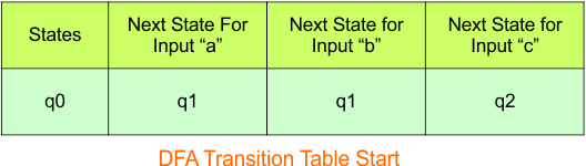
Step 3.2: Only “q0” exists in the state column of the DFA. However, the states “q1” and “q2” occur in the DFA table but do not appear in the state column. Therefore, we should simply add these states to the state column.
Transition at state “q1” against all inputs “a”, “b”, and “c”
For input “a”
δ([q1], a) = {ϕ}
For input “b”
δ([q1], b) = {q3}
For input “c”
δ([q1], c) = {ϕ}
Transition at state “q2” against all inputs “a”, “b”, and “c”
For input “a”
δ([q2], a) = {q3}
For input “b”
δ([q2], b) = {ϕ}
For input “c”
δ([q2], c) = {q1q3}
The updated DFA Table is given below
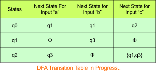
Repeat Step 3.2: State “q0”, “q1”, and “q2” exist in the state column of the DFA. However, the states “q3” and “q1q3” appear in the DFA table but are not listed in the state column. Therefore, we should add these states to the state column.
Transition at state “q3” against all inputs “a”, “b”, and “c”
For input “a”
δ([q3], a) = {ϕ}
For input “b”
δ([q3], b) = {q4}
For input “c”
δ([q3], c) = {q4}
Transition at state “q1q3” against all inputs “a”, “b”, and “c”
For input “a”
δ([q1q3], a) = δ(q1, a) ∪ δ(q3, a)
= {ϕ} ∪ {ϕ}
= {ϕ}
For input “b”
δ([q1q3], b) = δ(q1, b) ∪ δ(q3, b)
= {q3} ∪ {q4}
= {q3q4}
For input “c”
δ([q1q3], c) = δ(q1, c) ∪ δ(q3, c)
= {ϕ} ∪ {q4}
= {q4}
The updated DFA Table is given below
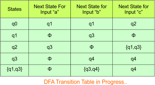
Repeat Step 3.2: State “q0”, “q1”, “q2”, “q3”, and “q1q3” exist in the state column of the DFA. However, the states “q4” and “q3q4” appear in the DFA table but are not listed in the state column. Therefore, we should add these states to the state column.
Transition at state “q4” against all inputs “a”, “b”, and “c”
For input “a”
δ([q4], a) = {q4}
For input “b”
δ([q4], b) = {q4}
For input “c”
δ([q4], c) = {q4}
Transition at state “q3q4” against all inputs “a”, “b”, and “c”
For input “a”
δ([q3q4], a) = δ(q3, a) ∪ δ(q4, a)
= {ϕ} ∪ {q4}
= {q4}
For input “b”
δ([q3q4], b) = δ(q3, b) ∪ δ(q4, b)
= {q4} ∪ {q4}
= {q4}
For input “c”
δ([q3q4], c) = δ(q3, c) ∪ δ(q4, c)
= {q4} ∪ {q4}
= {q4}
The updated DFA Table is given below
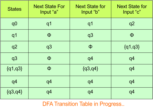
Repeat Step 3.2: No new state exists in the DFA table, except ϕ. Transition at “ϕ” against all inputs will always stay at “ϕ”. The updated DFA Table is given below
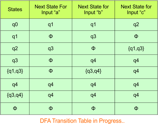
Step 3.3: At this stage, all newly generated states in the DFA table are executed successfully for their transitions, so the DFA table is ready.
Important: As q4 was the final state in NFA Table. That’s why, all those states will be the final states where q4 is present. Simply mark with “*” to represent the final state.
So, the following is the updated table of the DFA with its final states
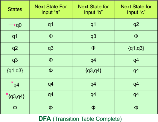
Step 4: Now draw the DFA according to the DFA Transition Table
According to the DFA transition table, we can generate the following DFA diagram
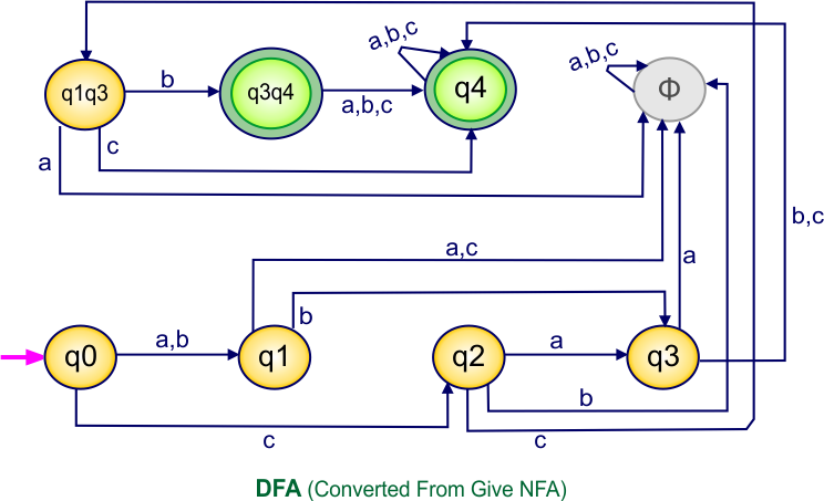
NFA to DFA Conversion Example: 11.4
Step 01: Draw NFA Graph
The following is the NFA graph that needs to be converted to a DFA.
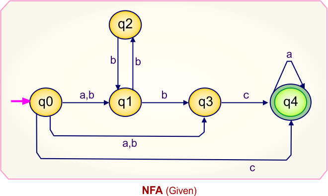
Step 02: Draw the NFA Transition Table.
The NFA transition table of the above NFA is given below
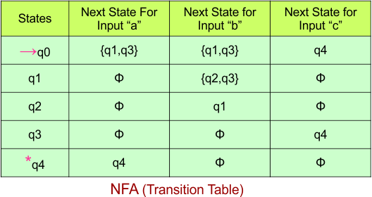
Step 03: Conversion of NFA to DFA Transition Table
Step 3.1:Select the first two rows of the NFA transition table, which will become the first two rows of the DFA transition table.
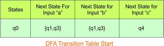
Step 3.2: Only “q0” exists in the state column of the DFA. However, the states “q1q3” and “q4” occur in the DFA table but do not appear in the state column. Therefore, we should simply add these states to the state column.
Transition at state “q1q3” against all inputs “a”, “b”, and “c”
For input “a”
δ([q1q3], a) = δ(q1, a) ∪ δ(q3, a)
= {ϕ} ∪ {ϕ}
= {ϕ}
For input “b”
δ([q1q3], b) = δ(q1, b) ∪ δ(q3, b)
= {q2q3} ∪ {ϕ}
= {q2q3}
For input “c”
δ([q1q3], c) = δ(q1, c) ∪ δ(q3, c)
= {ϕ} ∪ {q4}
= {q4}
Transition at state “q4” against all inputs “a”, “b”, and “c”
For input “a”
δ([q4], a) = {q4}
For input “b”
δ([q4], b) = {ϕ}
For input “c”
δ([q4], c) = {ϕ}
The updated DFA Table is given below
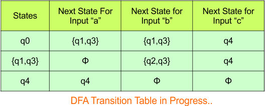
Repeat Step 3.2: State “q0”, “q1q3”, and “q4” exist in the state column of the DFA. However, the state “q2q3” appears in the DFA table but is not listed in the state column. Therefore, we should add this state to the state column.
Transition at state “q2q3” against all inputs “a”, “b”, and “c”
For input “a”
δ([q2q3], a) = δ(q2, a) ∪ δ(q3, a)
= {ϕ} ∪ {ϕ}
= {ϕ}
For input “b”
δ([q2q3], b) = δ(q2, b) ∪ δ(q3, b)
= {q1} ∪ {ϕ}
= {q1}
For input “c”
δ([q2q3], c) = δ(q2, c) ∪ δ(q3, c)
= {ϕ} ∪ {q4}
= {q4}
The updated DFA Table is given below
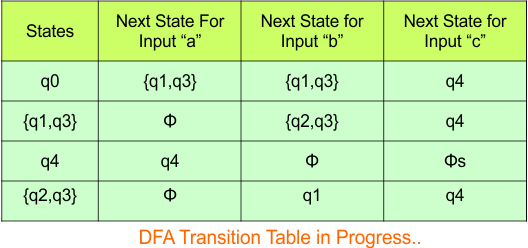
Repeat Step 3.2: State “q0”, “q1”, “q2”, “q3”, and “q1q3” exist in the state column of the DFA. However, the states “q4” and “q3q4” appear in the DFA table but are not listed in the state column. Therefore, we should add these states to the state column.
Transition at state “q1” against all inputs “a”, “b”, and “c”
For input “a”
δ([q1], a) = {ϕ}
For input “b”
δ([q1], b) = {q2q3}
For input “c”
δ([q1], c) = {ϕ}
The updated DFA Table is given below
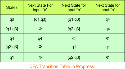
Repeat Step 3.2: No new state exists in the DFA table, except ϕ. Transition at “ϕ” against all inputs will always stay at “ϕ”. The updated DFA Table is given below
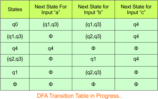
Step 3.3: At this stage, all newly generated states in the DFA table are executed successfully for their transitions, so the DFA table is ready.
Important: As q4 was the final state in NFA Table. That’s why, all those states will be the final states where q4 is present. Simply mark with “*” to represent the final state.
So, the following is the updated table of the DFA with its final states

Step 4: Now draw the DFA according to the DFA Transition Table
According to the DFA transition table, we can generate the following DFA diagram
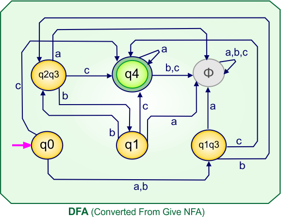
NFA to DFA Conversion Example: 11.5
Step 01: Draw NFA Graph
The following is the NFA graph that needs to be converted to a DFA.
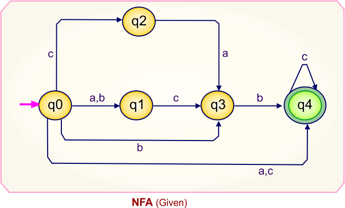
Step 02: Draw the NFA Transition Table.
The NFA transition table of the above NFA is given below
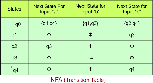
Step 03: Conversion of NFA to DFA Transition Table
Step 3.1:Select the first two rows of the NFA transition table, which will become the first two rows of the DFA transition table.
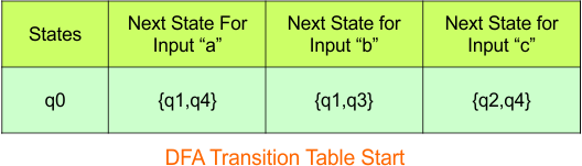
Step 3.2: Only “q0” exists in the state column of the DFA. However, the states “q1q4”, “q1q3“, and “q2q4” occur in the DFA table but do not appear in the state column. Therefore, we should simply add these states to the state column.
Transition at state “q1q4” against all inputs “a”, “b”, and “c”
For input “a”
δ([q1q4], a) = δ(q1, a) ∪ δ(q4, a)
= {ϕ} ∪ {ϕ}
= {ϕ}
For input “b”
δ([q1q4], b) = δ(q1, b) ∪ δ(q4, b)
= {ϕ} ∪ {ϕ}
= {ϕ}
For input “c”
δ([q1q4], c) = δ(q1, c) ∪ δ(q4, c)
= {q3} ∪ {q4}
= {q3q4}
Transition at state “q1q3” against all inputs “a”, “b”, and “c”
For input “a”
δ([q1q3], a) = δ(q1, a) ∪ δ(q3, a)
= {ϕ} ∪ {ϕ}
= {ϕ}
For input “b”
δ([q1q3], b) = δ(q1, b) ∪ δ(q3, b)
= {ϕ} ∪ {q4}
= {q4}
For input “c”
δ([q1q3], c) = δ(q1, c) ∪ δ(q3, c)
= {q3} ∪ {ϕ}
= {q3}
Transition at state “q2q4” against all inputs “a”, “b”, and “c”
For input “a”
δ([q2q4], a) = δ(q2, a) ∪ δ(q4, a)
= {q3} ∪ {ϕ}
= {q3}
For input “b”
δ([q2q4], b) = δ(q2, b) ∪ δ(q4, b)
= {ϕ} ∪ {ϕ}
= {ϕ}
For input “c”
δ([q2q4], c) = δ(q2, c) ∪ δ(q4, c)
= {ϕ} ∪ {q4}
= {q4}
The updated DFA Table is given below
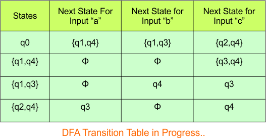
Repeat Step 3.2: State “q0”, “q1q4”, “q1q3”, and “q2q4” exist in the state column of the DFA. However, the states “q3”, “q4”, and “q3q4” appear in the DFA table but are not listed in the state column. Therefore, we should add these states to the state column.
Transition at state “q3q4” against all inputs “a”, “b”, and “c”
For input “a”
δ([q3q4], a) = δ(q3, a) ∪ δ(q4, a)
= {ϕ} ∪ {ϕ}
= {ϕ}
For input “b”
δ([q3q4], b) = δ(q3, b) ∪ δ(q4, b)
= {q4} ∪ {ϕ}
= {q4}
For input “c”
δ([q3q4], c) = δ(q3, c) ∪ δ(q4, c)
= {ϕ} ∪ {q4}
= {q4}
Transition at state “q3” against all inputs “a”, “b”, and “c”
For input “a”
δ([q3], a) = {ϕ}
For input “b”
δ([q3], b) = {q4}
For input “c”
δ([q3], c) = {ϕ}
Transition at state “q4” against all inputs “a”, “b”, and “c”
For input “a”
δ([q4], a) = {ϕ}
For input “b”
δ([q4], b) = {ϕ}
For input “c”
δ([q4], c) = {q4}
The updated DFA Table is given below

Repeat Step 3.2: No new state exists in the DFA table, except ϕ. Transition at “ϕ” against all inputs will always stay at “ϕ”. The updated DFA Table is given below
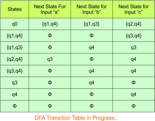
Step 3.3: At this stage, all newly generated states in the DFA table are executed successfully for their transitions, so the DFA table is ready.
Important: As q4 was the final state in NFA Table. That’s why, all those states will be the final states where q4 is present. Simply mark with “*” to represent the final state.
So, the following is the updated table of the DFA with its final states

Step 4: Now draw the DFA according to the DFA Transition Table
According to the DFA transition table, we can generate the following DFA diagram
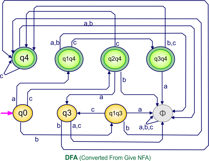
NFA to DFA Category-11 Examples: 5-States, 4-Input Symbols
Category 11 covers NFA to DFA conversions for machines with five states over the three input alphabets {a,b,c}.
NFA to DFA Conversion Example 11.1
Step 01: Draw NFA Graph
The following is the NFA graph that needs to be converted to a DFA.
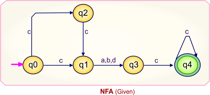
Step 02: Draw the NFA Transition Table.
The NFA transition table of the above NFA is given below
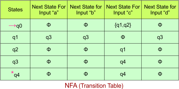
Step 03: Conversion of NFA to DFA Transition Table
Step 3.1:Select the first two rows of the NFA transition table, which will become the first two rows of the DFA transition table.

Step 3.2: Only “q0” exists in the state column of the DFA. However, the state “q1q2” occurs in the DFA table but does not appear in the state column. Therefore, we should simply add this state to the state column. The transitions for “q1q2” are given below
Transition at state “q2q4” against all inputs “a”, “b”, “c”, and “d”
For input “a”
δ([q1q2], a) = δ(q1, a) ∪ δ(q2, a)
= {q3} ∪ {ϕ}
= {q3}
For input “b”
δ([q1q2], b) = δ(q1, b) ∪ δ(q2, b)
= {q3} ∪ {ϕ}
= {q3}
For input “c”
δ([q1q2], c) = δ(q1, c) ∪ δ(q2, c)
= {ϕ} ∪ {q1}
= {q1}
For input “d”
δ([q1q2], c) = δ(q1, c) ∪ δ(q2, c)
= {q3} ∪ {ϕ}
= {q3}
The updated DFA Table is given below

Repeat Step 3.2: State “q0” and “q1q2” exist in the state column of the DFA. However, the states “q3” and “q1” occur in the DFA table but do not appear in the state column. Therefore, we should add these states to the state column.
Transition at state “q3”
For input “a”
δ([q3], a) = {q0}
For input “b”
δ([q3], b) = {ϕ}
For input “c”
δ([q3], c) = {q4}
For input “d”
δ([q3], d) = {ϕ}
Transition at state “q1“
For input “a”
δ([q1], a) = {q3}
For input “b”
δ([q1], b) = {q3}
For input “c”
δ([q1], c) = {ϕ}
For input “d”
δ([q1], d) = {q3}
The updated DFA Table is given below

Repeat Step 3.2: State “q0”, “q1“, “q3”, and “q1q4” exist in the state column of the DFA. However, the state “q4” occurs in the DFA table but does not appear in the state column. Therefore, we should add these states to the state column.
Transition at state “q4”
For input “a”
δ([q4], a) = {ϕ}
For input “b”
δ([q4], b) = {ϕ}
For input “c”
δ([q4], c) = {q4}
For input “d”
δ([q4], d) = {ϕ}
The updated DFA Table is given below

In the above DFA Table
- State Column Contains: “q0”, “q1q2”, “q1”, “q3”, “q4”
- Input columns contain: “q0”, “q1q2”, “q1”, “q3”, “q4”
Repeat Step 3.2: No new state exists in the DFA table, except ϕ. Transition at “ϕ” against all inputs will always stay at “ϕ”. The updated DFA Table is given below

Step 3.3: At this stage, all newly generated states in the DFA table are executed successfully for their transitions, so the DFA table is ready.
Important: As q4 was the final state in NFA Table. That’s why, all those states will be the final states where q4 is present. Simply mark with “*” to represent the final state.
So, the following is the updated table of the DFA with its final states
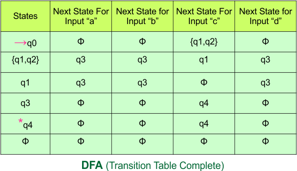
Step 4: Now draw the DFA according to the DFA Transition Table
According to the DFA transition table, we can generate the following DFA diagram.
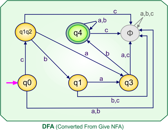
NFA to DFA Conversion Example 11.2
Step 01: Draw NFA Graph
The following is the NFA graph that needs to be converted to a DFA.
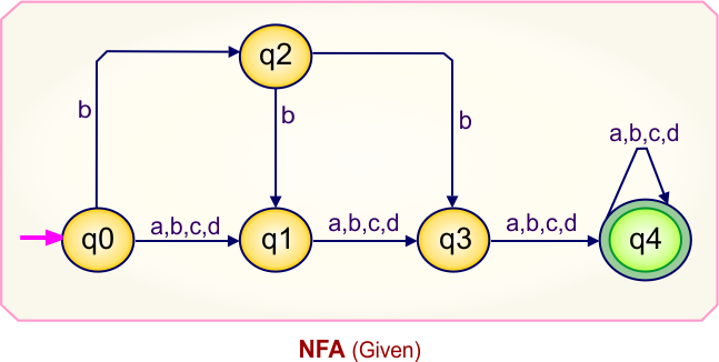
Step 02: Draw the NFA Transition Table.
The NFA transition table of the above NFA is given below

Step 03: Conversion of NFA to DFA Transition Table
Step 3.1:Select the first two rows of the NFA transition table, which will become the first two rows of the DFA transition table.
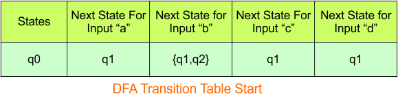
Step 3.2: Only “q0” exists in the state column of the DFA. However, the states “q1” and “q1q2” occur in the DFA table but do not appear in the state column. Therefore, we should simply add these states to the state column.
Transition at state “q1q2”
For input “a”
δ([q1q2], a) = δ(q1, a) ∪ δ(q2, a)
= {q3} ∪ {ϕ}
= {q3}
For input “b”
δ([q1q2], b) = δ(q1, b) ∪ δ(q2, b)
= {q3} ∪ {q1q3}
= {q1q3}
For input “c”
δ([q1q2], c) = δ(q1, c) ∪ δ(q2, c)
= {q3} ∪ {ϕ}
= {q3}
For input “d”
δ([q1q2], c) = δ(q1, c) ∪ δ(q2, c)
= {q3} ∪ {ϕ}
= {q3}
Transition at state “q1“
For input “a”
δ([q1], a) = {q3}
For input “b”
δ([q1], b) = {q3}
For input “c”
δ([q1], c) = {q3}
For input “d”
δ([q1], d) = {q3}
The updated DFA Table is given below
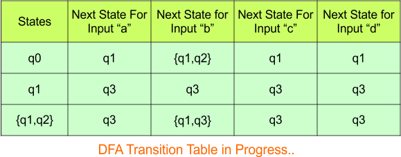
Repeat Step 3.2: State “q0″ ,”q1”, and “q1q2” exist in the state column of the DFA. However, the states “q3” and “q1q3” occur in the DFA table but do not appear in the state column. Therefore, we should add these states to the state column.
Transition at state “q3”
For input “a”
δ([q3], a) = {q4}
For input “b”
δ([q3], b) = {q4}
For input “c”
δ([q3], c) = {q4}
For input “d”
δ([q3], d) = {q4}
Transition at state “q1q3”
For input “a”
δ([q1q3], a) = δ(q1, a) ∪ δ(q3, a)
= {q3} ∪ {q4}
= {q3q4}
For input “b”
δ([q1q3], b) = δ(q1, b) ∪ δ(q3, b)
= {q3} ∪ {q4}
= {q3q4}
For input “c”
δ([q1q3], c) = δ(q1, c) ∪ δ(q3, c)
= {q3} ∪ {q4}
= {q3q4}
For input “d”
δ([q1q3], c) = δ(q1, c) ∪ δ(q3, c)
= {q3} ∪ {q4}
= {q3q4}
The updated DFA Table is given below
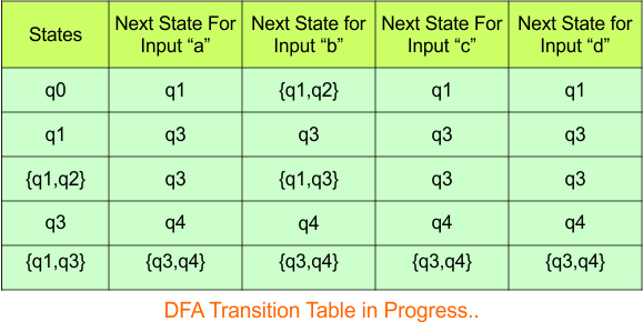
Repeat Step 3.2: State “q0”, “q1“, “q3”, “q1q2”, and “q1q3” exist in the state column of the DFA. However, the states “q4” and “q3q4” occur in the DFA table but do not appear in the state column. Therefore, we should add these states to the state column.
Transition at state “q4”
For input “a”
δ([q4], a) = {q4}
For input “b”
δ([q4], b) = {q4}
For input “c”
δ([q4], c) = {q4}
For input “d”
δ([q4], d) = {q4}
The updated DFA Table is given below
Transition at state “q3q4”
For input “a”
δ([q3q4], a) = δ(q3, a) ∪ δ(q4, a)
= {q4} ∪ {q4}
= {q4}
For input “b”
δ([q3q4], b) = δ(q3, b) ∪ δ(q4, b)
= {q4} ∪ {q4}
= {q4}
For input “c”
δ([q3q4], c) = δ(q3, c) ∪ δ(q4, c)
= {q4} ∪ {q4}
= {q4}
For input “d”
δ([q3q4], c) = δ(q3, c) ∪ δ(q4, c)
= {q4} ∪ {q4}
= {q4}
The updated DFA Table is given below
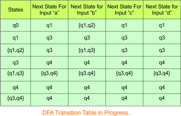
Step 3.3: At this stage, all newly generated states in the DFA table are executed successfully for their transitions, so the DFA table is ready.
Important: As q4 was the final state in NFA Table. That’s why, all those states will be the final states where q4 is present. Simply mark with “*” to represent the final state.
So, the following is the updated table of the DFA with its final states

Step 4: Now draw the DFA according to the DFA Transition Table
According to the DFA transition table, we can generate the following DFA diagram.
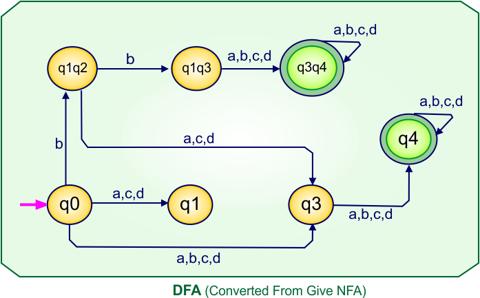
Practice Question: NFA to DFA Conversions
Step 01: Draw NFA Graph
The following is the NFA graph that needs to be converted to a DFA.
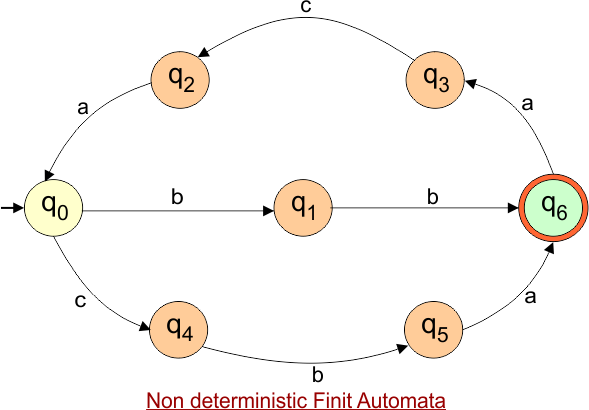
Step 02: Draw the NFA Transition Table.
The NFA transition table of the above NFA is given below
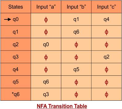
I kindly request that you complete Example 18, which involves converting an NFA to a DFA. Once you’ve finished, please send it to me for verification. Your effort is greatly appreciated!
| Note: Hence proved that,
DFA has a higher number of states as compared to NFA states. If “n” is the maximum number of states in NFA, then 2n is the maximum number of states in its corresponding DFA. |
NFA to DFA Conversion Findings
After converting an NFA to a DFA, you get the following outcomes in terms of states and other key points:
Conclusion
Converting an NFA to a DFA is a process that can be efficiently done using the subset construction method. While the NFA allows for multiple transitions from a given state, the DFA ensures that there is exactly one transition per state for each symbol. This conversion helps in optimizing the performance of automata in practical applications like lexical analysis, pattern matching, and more.