
Common Bus System using Multiplexer (4-bit, 8-bit)
The concept of working a common bus system using a multiplexer in 4 bits, 8 bits, or 16 bits is almost the same. This article will teach us about 4-bit and 8-bit register architecture, but most registers are 16-bit in computer architecture.
Generally, computers use many registers for different purposes. We need to transfer the data and instructions between these registers. So, To transfer the data between the registers, the common bus system is used. For this purpose, we connect all registers with a common BUS through Multiplexer.
4-bit register in the Common Bus System
The 4-bit register means that the size of the register is 4-bit. These 4-bit registers use four multiplexers because the number of bits in the register always equals the number of multiplexers. This mechanism is also known as a “4×1” multiplexer. The 4×1 Multiplexer means four inputs to each Multiplexer from four registers and one output to the common bus.
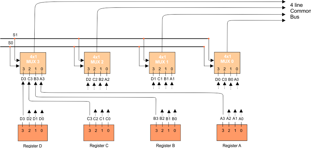
As in the above diagram, four registers and four multiplexers, each register of 4 bits, numbering from 0 to 3. There are two select lines, S0 and S1.
How Registers and multiplexers are connected?
The bits of Register A are (A3, A2, A1, A0). Register B is (B3, B2, B1, and B0). Register C is (C3, C2, C1, and C0). And Register D is (D3, D2, D1, and D0).
And the first Multiplexer is (D0, C0, B0, and A0). The second Multiplexer is (D1, C1, B1, and A1). The third Multiplexer is (D3, C3, B3, and A3). The fourth Multiplexer is (D4, C4, B4, and A4).
If we connect the first Multiplexer with registers, then fetch all zero bits from all registers and connect them to the first Multiplexer. In some way, if we want to connect the second Multiplexer with registers, then fetch all bits from position 1 of all registers, connect them to the 2nd Multiplexer, and so on for other registers and multiplexer connections.
How are the bits transferred from the Multiplexer to the common bus?
We assign values to the select lines connected to each Multiplexer. So, the value of the select line activates the relevant bit of each Multiplexer and transfers it to the common bus. Here’s a table that shows all combinations of select lines (S1S0).
| SELECT LINES COMBINATION S1S0 | SELECTED REGISTER TO TRANSFER DATA |
| 00 | Register A |
| 01 | Register B |
| 10 | Register C |
| 11 | Register D |
When S1S0=00, then Register “A” is activated. The select lines are linked to each Multiplexer, activating the zero (0) bit in every Multiplexer, as each zero bit is connected to register A. So, one output from each Multiplexer will be sent to the common bus, as shown in the following diagram.
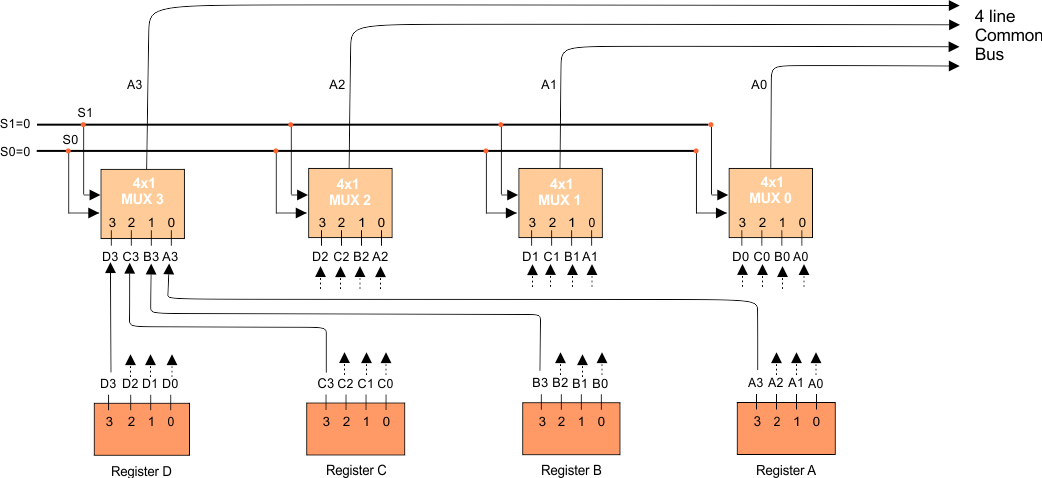
Output “A3” from Multiplexer 3, Output “A2” from Multiplexer 2, Output “A1” from Multiplexer 1, and Output “A0” from Multiplexer 0 arrive at common bus from 4 multiplexers which are the values of register A. Register A’s data is now loaded onto a common bus, accessible to any other register in the system or any other part, such as the ALU, memory, etc. The same process applies to the remaining registers.
Look at another example: when S1S0=11, register D is selected, and it can transfer data to the common bus. When you set S1S0 to 11, the common bus receives the third data input from all the multiplexers. As we know, 11 in a binary number system equals 3 in decimal.
As the 3rd data input of all the multiplexers receives the inputs from register D, register D gets selected, just like the same case with other registers.
Number of multiplexers needed = number of bits in each register
Number of inputs in each multiplexer needed = Total number of registers.
Explanation of 8×1 Multiplexer
If the register size is 8 Bits and there are four registers, then a connection to the common bus is shown in the following diagram.
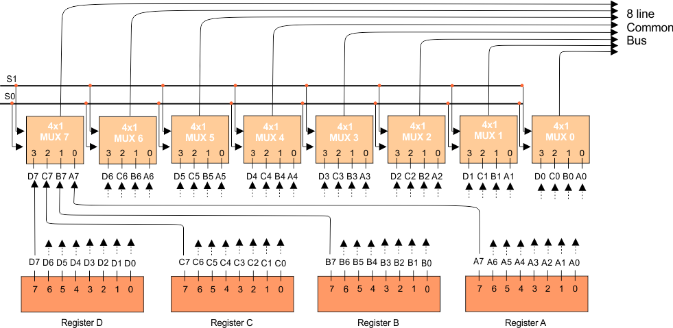
As there are four registers, the number of inputs to each Multiplexer is four, and the total number of bits in each register is 8. So, the total Multiplexer will be 8. As there are four registers, two select lines (two bits) are enough to represent these four registers.
8×1 Multiplexer with Example
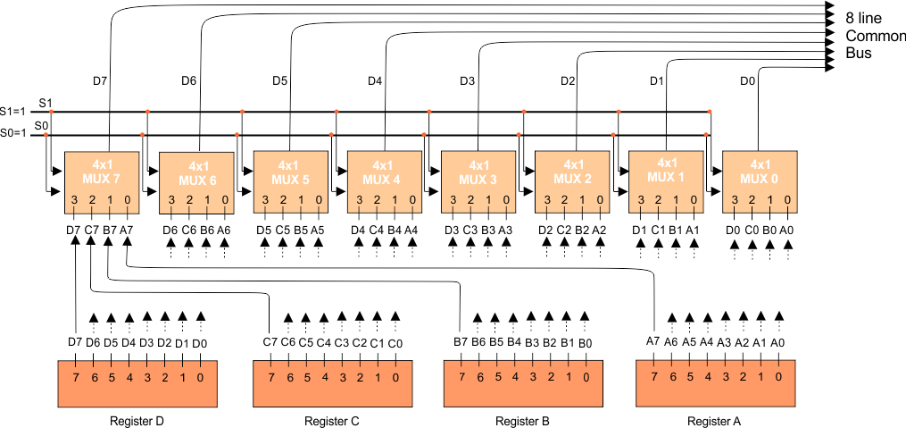
Assume that setting S1S0 to 11 activates Register D. The following diagram illustrates one output from each multiplexer of Register D to the common bus.
Question: How do registers communicate with each other through a common bus?
Answer: We connect all registers with a common bus through the multiplexers.
Note: If a common bus has eight registers of 16 bits, it requires 16 multiplexers. Each multiplexer will contain eight data input lines and three selection lines (S2, S1, and S0).