


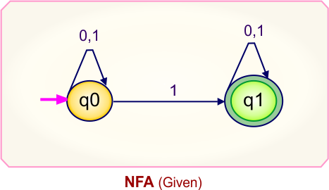
NFA To DFA Examples
In this lecture, we will see NFA to DFA examples with simple, step-by-step conversions using an algorithm.We found the followng after NFA to DFA conversion
-
The number of states in the DFA may be different from the NFA.
-
If an NFA has m states, the DFA can have at most 2ᵐ states.
-
The number of DFA states (n) satisfies: 1 ≤ n ≤ 2ᵐ
Where:
-
n = number of DFA states
-
m = number of NFA states
-
-
Every NFA can always be transformed into an equivalent DFA.
Convert NFA to DFA – Algorithm
There are four basic steps for the conversion of NFA to DFA.
- Step 01: Start with the given NFA diagram.
- Step 02: Prepare the transition table from the NFA diagram.
- Step 03: Build the NFA transition table to the DFA transition Table.
- Step 3.1: Find the ε-closure of the NFA’s start state. Include all states reachable through epsilon (ε) transitions. This group of states becomes the initial state of the DFA.
- Step 3.2: Check each entry in the DFA table. If a combination of states appears in the input column but not in the states column, it is a new DFA state. Add this new state to the states column. Determine its transitions using the NFA transition table. Continue this process until no new states appear.
- Step 3.3: If “x” was the final state in the NFA Transition Table, then all those states will be the final states in the DFA Transition Table where “x” exists.
- Step 04: Convert the DFA table to the DFA Diagram.
NFA to DFA Conversion – Key Observations
When we convert a Non-Deterministic Finite Automaton (NFA) into a Deterministic Finite Automaton (DFA), several important changes occur:
1. Number of States
If the NFA has n states, the DFA can have up to 2ⁿ states.
Each DFA state represents a subset (combination) of NFA states, including all possible groupings.
2. Deterministic Transitions
In a DFA, every state has exactly one transition for each input symbol.
There are no multiple paths or ambiguity like in an NFA.
3. Start State
The starting state of the DFA is formed by:
-
The NFA’s initial state
-
All states reachable from it through epsilon (ε) transitions, if they exist
This set becomes the DFA’s initial state.
4. Accepting States
A DFA state is marked as accepting (final) if it contains at least one accepting state of the NFA inside its subset.
5. No Epsilon Moves
Unlike NFAs, DFAs do not allow epsilon (ε) transitions.
All transitions must occur on actual input symbols.
6. Increase in Size
The DFA may have more states than the original NFA because it includes all possible combinations of NFA states. In some cases, the increase can be significant.
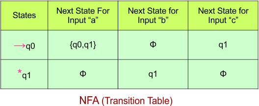
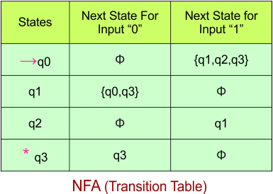
NFA To DFA Example: 01
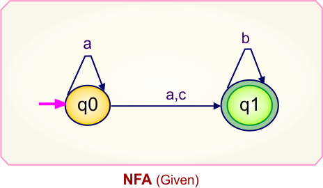
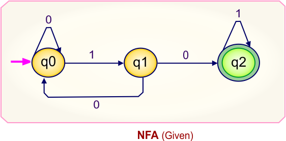
Step 01: Draw NFA Graph
The graph below represents an NFA that needs conversion into a DFA.
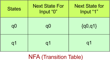
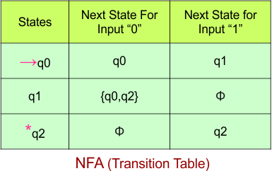
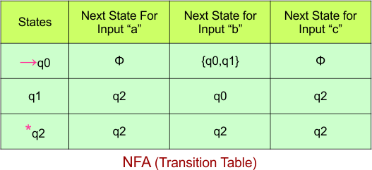
Step 02: Draw the NFA Transition Table.
The table below presents the transition table of the NFA derived from the given NFA.
Step 03: Conversion of NFA to DFA Transition Table
Let’s begin converting the NFA transition table to the DFA transition table.
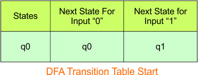
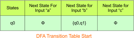
Step 3.1: Select the first two rows of the NFA transition table to form the initial two rows of the DFA transition table below.
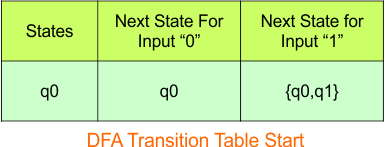
In the above DFA Table
- State Column Contains: “q0”
- Input columns contain: “q0”, “q0q1”
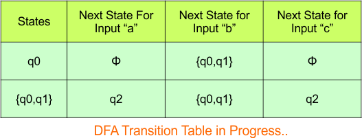
Step 3.2: State “q0q1” is a new state because it appears in the input columns of the DFA but does not exist in the state column. Add “q0q1” to the state column along with its transitions.
Transition calculations at state “q0q1”
For input “0”
δ([q0q1], 0) = δ(q0, 0) ∪ δ(q1, 0)
= {q0} ∪ {q1}
= {q0q1}
For input “1”
δ([q0q1], 1) = δ(q0, 1) ∪ δ(q1, 1)
= {q0q1} ∪ {q1}
= {q0q1}
The updated DFA table is given below.
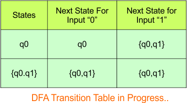
In the above DFA Table
- State Column Contains: “q0”, “q0q1”
- Input columns contain: “q0”, “q0q1”
At this stage, no new states remain for the state column. The DFA table is just one step away from completion.
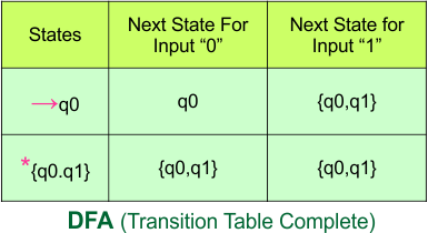
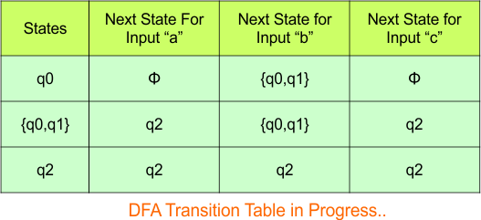
Step 3.3: State “q1” was the final state in the NFA table. Therefore, all states will be final states where “q1” appears in the DFA state column. Simply mark these states with “*” to indicate they are final states.
Here is the updated DFA table, which includes all of its final states.
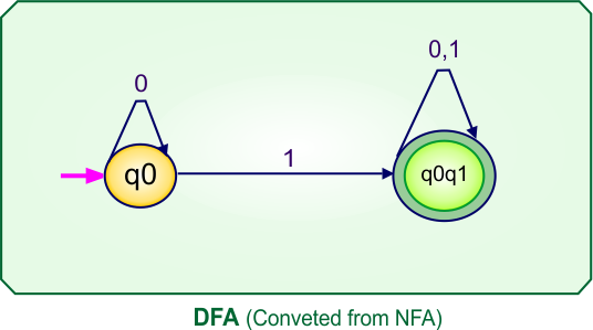
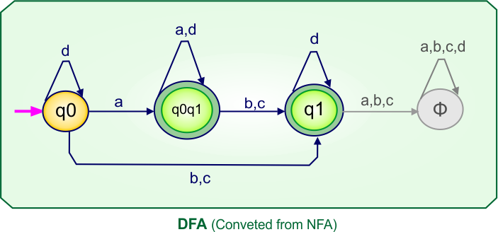
Step 4: Now, draw the DFA according to the DFA transition table
The following is the converted Deterministic Finite Automaton (DFA) derived from the given Nondeterministic Finite Automaton (NFA).
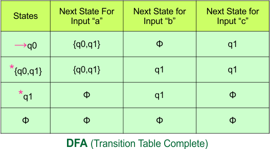
NFA To DFA Example: 02
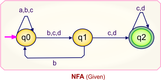
Step 01: Draw NFA Graph
The following is the NFA graph that needs to be converted to a DFA.
Step 02: Draw the NFA transition Table.
The NFA transition table of the above NFA is given below
Step 03: Conversion of NFA to DFA Transition Table
Step 3.1: Select the first two rows of the NFA transition table, which will become the first two rows of the DFA transition table.
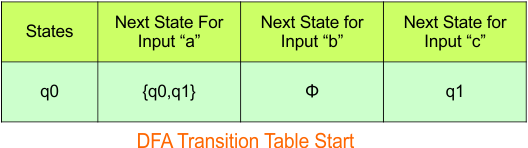
In the above DFA Table
- State Column Contains: “q0”
- Input columns contain: “q0q1”, “q1”
Step 3.2: States “q0q1” and “q1” are new states because they are present in the DFA’s input columns but do not exist in the state column. Add states “q0q1” and “q1” along with their transitions to the state column.
Transition calculations for state “q0q1”
For input “a”
δ([q0q1], a) = δ(q0, a) ∪ δ(q1, a)
= {q0q1} ∪ {ϕ}
= {q0q1}
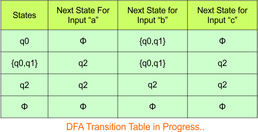
For input “b”
δ([q0q1], b) = δ(q0, b) ∪ δ(q1, b)
= {ϕ} ∪ {q1}
= {q1}
For input “c”
δ([q0q1], c) = δ(q0, c) ∪ δ(q1, c)
= {q1} ∪ {ϕ}
= {q1}
Transition at state “q1” against all inputs “a”, “b”, and “c”
For input “a”
δ([q1], a) = {ϕ}
For input “b”
δ([q1], b) = {q1}
For input “c”
δ([q1], c) = {ϕ}
Hence, the updated DFA table is given below.
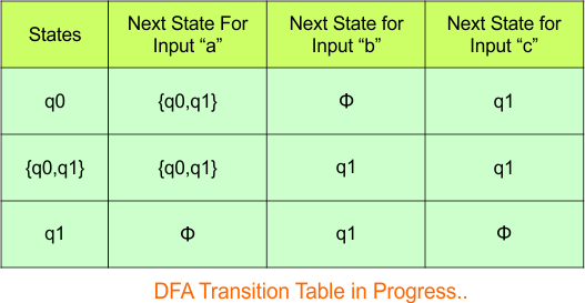
In the above DFA Table
- State Column Contains: “q0”, “q0q1”, “q1”
- Input columns contain: “q0”, “q0q1”, “q1”
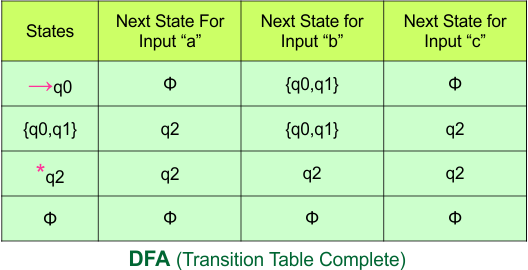
Repeat Step 3.2: No new state exists in the DFA table, except ϕ. Transition at “ϕ” against all inputs will always stay at “ϕ”. The updated DFA Table is given below
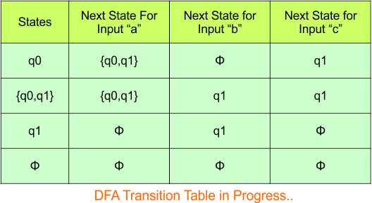
Step 3.3: At this stage, all newly generated states in the DFA table are executed successfully for their transitions, so the DFA table is ready.
Important: As “q1” was the final state in NFA Table. That’s why, all those states will be the final states where “q1” is present. Simply mark with “*” to represent the final state.
So, the following is the updated table of the DFA with its final states
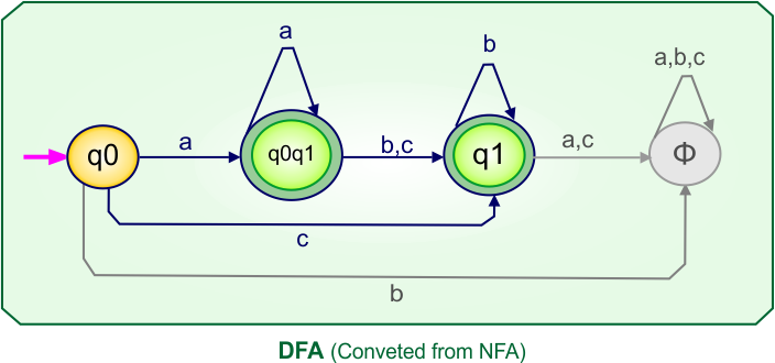
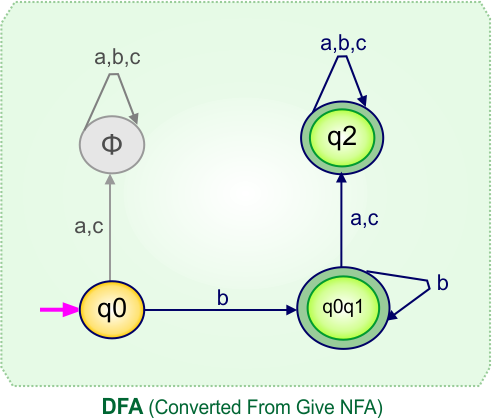
Step 4: Now draw the DFA according to the DFA Transition Table
According to the DFA transition table, we can generate the following DFA diagram.
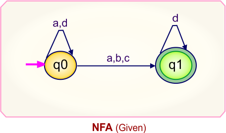
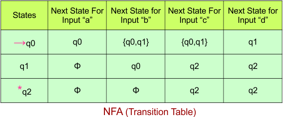
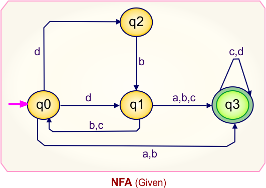
NFA To DFA Example: 03
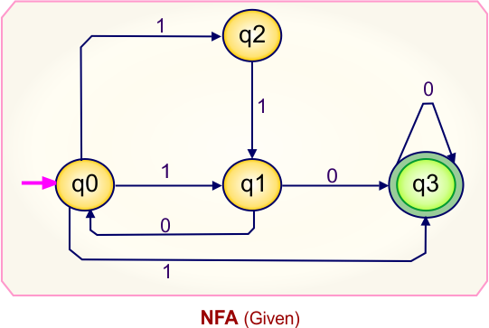
Step 01: Draw NFA Graph
The following is the NFA graph that needs to be converted to a DFA.
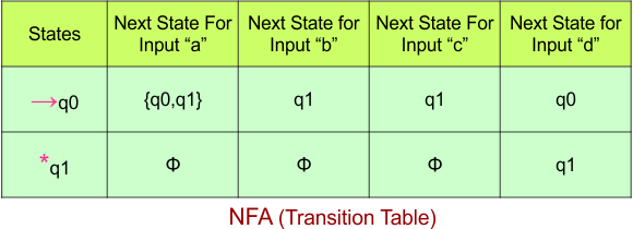
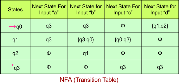
Step 02: Draw the NFA transition Table.
The NFA transition table of the above NFA is given below
Step 03: Conversion of NFA to DFA Transition Table
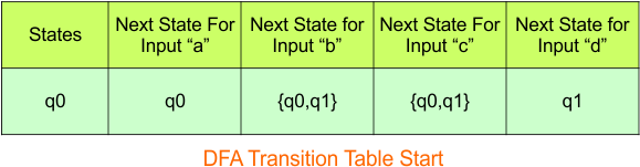
Step 3.1:Select the first two rows of the NFA transition table, which will become the first two rows of the DFA transition table.
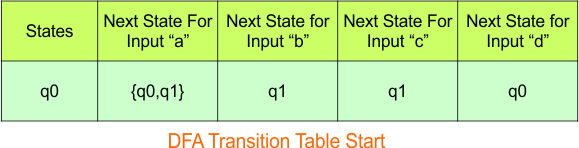
In the above DFA Table
- State Column Contains: “q0”
- Input columns contain: “q0q1”, “q1”, “q0”
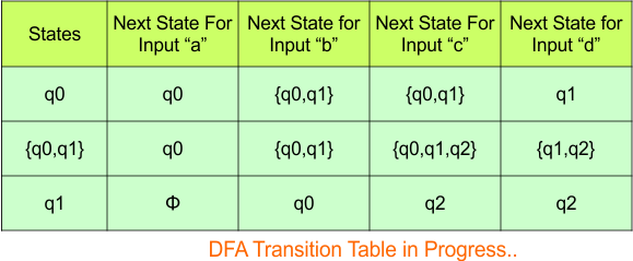
Step 3.2: States “q0q1” and “q1” are new states because they are present in the DFA’s input columns but do not exist in the state column. Add states “q0q1” and “q1” along with their transitions to the state column.
Transition at state “q0q1” against all inputs “a”, “b”, “c”, and “d” is given below
For input “a”
δ([q0q1], a) = δ(q0, a) ∪ δ(q1, a)
= {q0q1} ∪ {ϕ}
= {q0q1}
For input “b”
δ([q0q1], b) = δ(q0, b) ∪ δ(q1, b)
= {q1} ∪ {ϕ}
= {q1}
For input “c”
δ([q0q1], c) = δ(q0, c) ∪ δ(q1, c)
= {q1} ∪ {ϕ}
= {q1}
For input “d”
δ([q0q1], d) = δ(q0, d) ∪ δ(q1, d)
= {q0} ∪ {q1}
= {q0q1}
Transition at state “q” against all inputs “a”, “b”, “c”, and “d”
For input “a”
δ([q1], a) = {ϕ}
For input “b”
δ([q1], b) = {ϕ}
For input “c”
δ([q1], c) = {ϕ}
For input “d”
δ([q1], d) = {q1}
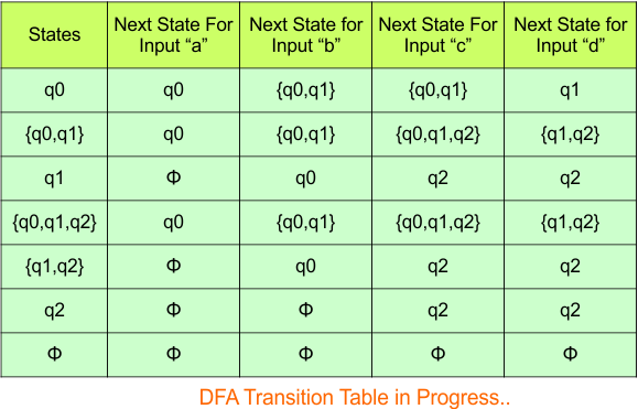
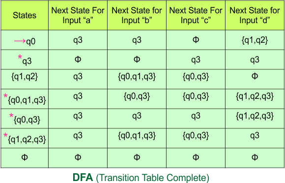
The updated DFA Table is given below
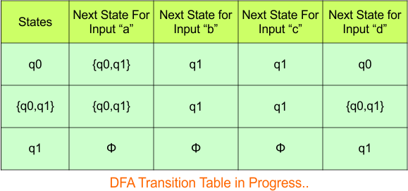
In the above DFA Table
- State Column Contains: “q0”, “q0q1”, “q1”
- Input columns contain: “q0”, “q0q1”, “q1”
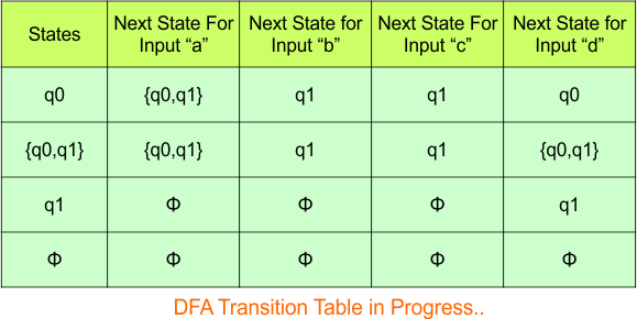
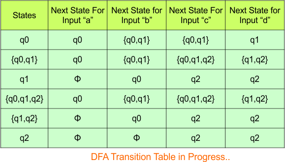
Repeat Step 3.2: No new states exist in the DFA table, except ϕ. The transition at “ϕ” for all inputs will always remain at “ϕ”. The updated DFA table is given below.
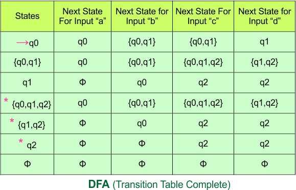
Step 3.3: At this stage, all newly generated states in the DFA table are executed successfully for their transitions, so the DFA table is ready.
Important: As “q1” was the final state in NFA Table. That’s why, all those states will be the final states where “q1” is present. Simply mark with “*” to represent the final state.
So, the following is the updated table of the DFA with its final states
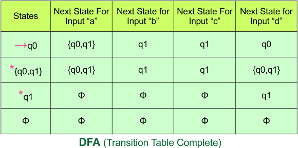
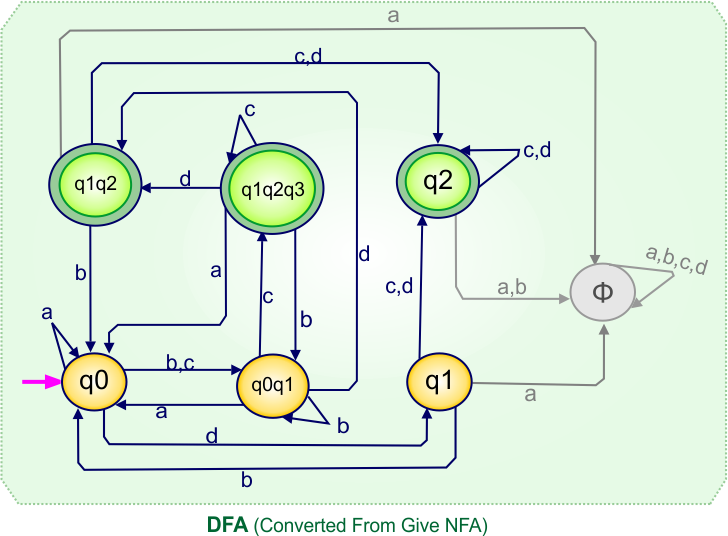
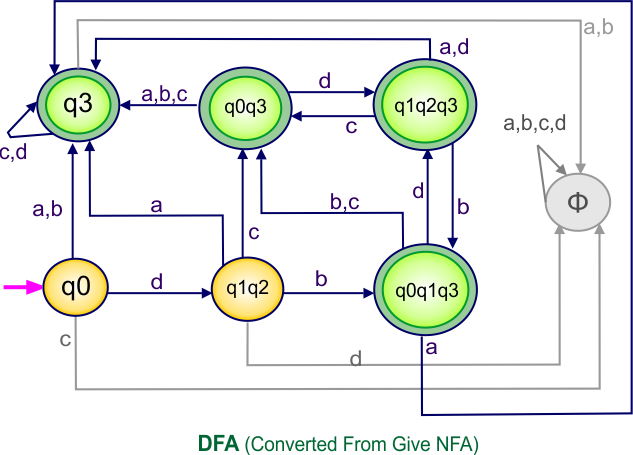
Step 4: Now draw the DFA according to the DFA Transition Table
According to the DFA transition table, we can generate the following DFA diagram.
NFA To DFA Example: 04
Step 01: Draw NFA Graph
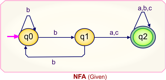
The graph below represents an NFA that needs conversion into a DFA.
Step 02: Draw the NFA Transition Table.
The table below presents the transition table of the NFA derived from the given NFA.
Step 03: Conversion of NFA to DFA Transition Table
Let’s begin converting the NFA transition table to the DFA transition table.
Step 3.1: Select the first two rows of the NFA transition table to form the initial two rows of the DFA transition table below.
In the above DFA Table
- State Column Contains: “q0”
- Input columns contain: “q0”, “q1”
Step 3.2: State “q1” is a new state because it appears in the input columns of the DFA but does not exist in the state column. Add “q1” to the state column along with its transitions.
Transition calculations at state “q1”
For input “0”
δ(q1, 0) = {q0q2}
For input “1”
δ(q1, 1) = {ϕ}
The updated DFA table is given below.
In the above DFA Table
- State Column Contains: “q0”, “q1”
- Input columns contain: “q0”, “q1”, “q0q2”
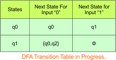
Repeat Step 3.2: “q0q2” is a new state because it is present in the input columns of the DFA but does not exist in the state column. Put “q0q2” in the state column along with their transitions.
Transition calculations at state “q0q2”
For input “0”
δ([q0q2], 0) = δ(q0, 0) ∪ δ(q2, 0)
= {q0} ∪ {ϕ}
= {q0}
For input “1”
δ([q0q2], 0) = δ(q0, 0) ∪ δ(q2, 0)
= {q1} ∪ {q2}
= {q1q2}
The updated DFA table is given below.
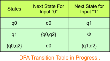
In the above DFA Table
- State Column Contains: “q0”, “q1”, “q0q2”
- Input columns contain: “q0”, “q1”, “q0q2”, “q1q2”
Repeat Step 3.2: “q1q2” is a new state because it is present in the input columns of the DFA but does not exist in the state column. Put “q1q2” in the state column along with their transitions.
Transition calculations at state “q1q2”
For input “0”
δ([q1q2], 0) = δ(q1, 0) ∪ δ(q2, 0)
= {q0q2} ∪ {ϕ}
= {q0q2}
For input “1”
δ([q1q2], 0) = δ(q1, 0) ∪ δ(q2, 0)
= {ϕ} ∪ {q2}
= {q2}
The updated DFA table is given below.
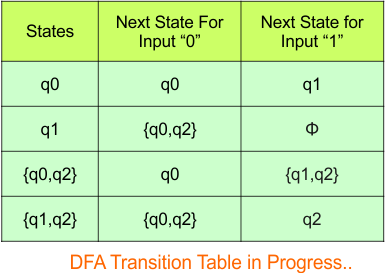
In the above DFA Table
- State Column Contains: “q0”, “q1”, “q0q2”, “q1q2”
- Input columns contain: “q0”, “q1”, “q0q2”, “q1q2”, “q2”
Repeat Step 3.2: “q2” is a new state because it is present in the input columns of the DFA but does not exist in the state column. Put “q2” in the state column along with its transitions.
Transition calculations at state “q2”
For input “0”
δ([q2], 0) = {ϕ}
For input “1”
δ([q2], 0) = {q2}
The updated DFA table is given below.
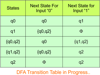
In the above DFA Table
- State Column Contains: “q0”, “q1”, “q0q2”, “q1q2”, “q2”
- Input columns contain: “q0”, “q1”, “q0q2”, “q1q2”, “q2”
Repeat Step 3.2: No new states exist in the DFA table, except ϕ. The transition at “ϕ” for all inputs will always remain at “ϕ”. The updated DFA table is given below.
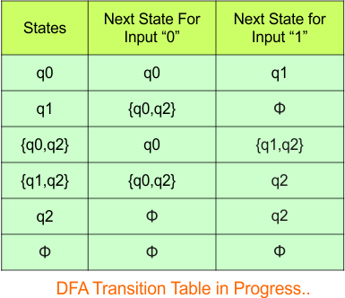
At this stage, no new states remain for the state column. The DFA table is just one step away from completion.
Step 3.3: State “q2” was the final state in the NFA table. Therefore, all states will be final states where “q2” appears in the DFA state column. Simply mark these states with “*” to indicate they are final states.
Here is the updated DFA table, which includes all of its final states.
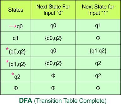
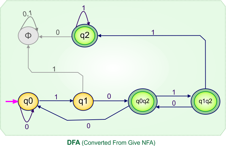
Step 4: Now draw the DFA according to the DFA transition table
The following is the converted Deterministic Finite Automaton (DFA) derived from the given Nondeterministic Finite Automaton (NFA).
NFA To DFA Example: 05
Step 01: Draw NFA Graph
The following is the NFA graph that needs to be converted to a DFA.
Step 02: Draw the NFA Transition Table.
The NFA transition table of the above NFA is given below
Step 03: Conversion of NFA to DFA Transition Table
Step 3.1: Select the first two rows of the NFA transition table, which will become the first two rows of the DFA transition table.
In the above DFA Table
- State Column Contains: “q0”
- Input columns contain: “q0”, “q0q1”
Step 3.2: State “q0q1” is a new state because it is present in the DFA’s input columns but does not exist in the state column. Put “q0q1” in the state column along with its transitions.
Transition calculations at state “q0q1”
For input “a”
δ([q0q1], a) = δ(q0, a) ∪ δ(q1, a)
= {ϕ} ∪ {q2}
= {q2}
For input “b”
δ([q0q1], b) = δ(q0, b) ∪ δ(q1, b)
= {q0q1} ∪ {q0}
= {q0q1}
For input “c”
δ([q0q1], c) = δ(q0, c) ∪ δ(q1, c)
= {ϕ} ∪ {q2}
= {q2}
Hence, the updated DFA table is given below.
In the above DFA Table
- State Column Contains: “q0”, “q0q1”
- Input columns contain: “q0”, “q0q1”, “q2”
Repeat Step 3.2: “q2” is a new state because it is present in the input columns of the DFA but does not exist in the state column. Put “q2” in the state column along with their transitions.
Transition calculations for state “q2”
For input “a”
δ([q2], a) = {q2}
For input “b”
δ([q2], b) = {q2}
For input “c”
δ([q2], c) = {q2}
The updated DFA Table is given below
In the above DFA Table
- State Column Contains: “q0”, “q0q1”, “q2”
- Input columns contain: “q0”, “q0q1”, “q2”
Repeat Step 3.2: No new state exists in the DFA table, except ϕ. Transition at “ϕ” against all inputs will always stay at “ϕ”. The updated DFA Table is given below
At this stage, no new state remains for the state column. The DFA table is one step away from being complete.
Step 3.3: At this stage, all newly generated states in the DFA table are executed successfully for their transitions, so the DFA table is ready.
Important: As “q2” was the final state in NFA Table. That’s why, all those states will be the final states where “q2” is present. Simply mark with “*” to represent the final state.
So, the following is the updated table of the DFA with its final states
Step 4: Now draw the DFA according to the DFA Transition Table
According to the DFA transition table, we can generate the following DFA diagram.
NFA To DFA Example: 06
Step 01: Draw NFA Graph
The following is the NFA graph that needs to be converted to a DFA.
Step 02: Draw the NFA Transition Table.
The NFA transition table of the above NFA is given below
Step 03: Conversion of NFA to DFA Transition Table
Step 3.1:Select the first two rows of the NFA transition table, which will become the first two rows of the DFA transition table.
In the above DFA Table
- State Column Contains: “q0”
- Input columns contain: “q0”, “q0q1”, “q1”
Repeat Step 3.2: States “q0q1” and “q1” are new states because they are present in the DFA’s input columns but do not exist in the state column. Add states “q0q1” and “q1” along with their transitions to the state column.
Transition at state “q0q1“
For input “a”
δ([q0q1], a) = δ(q0, a) ∪ δ(q1, a)
= {q0} ∪ {ϕ}
= {q0}
For input “b”
δ([q0q1], b) = δ(q0, b) ∪ δ(q1, b)
= {q0q1} ∪ {q1}
= {q0q1}
For input “c”
δ([q0q1], c) = δ(q0, c) ∪ δ(q1, c)
= {q0q1} ∪ {q2}
= {q0q1q2}
For input “d”
δ([q0q1], d) = δ(q0, d) ∪ δ(q1, d)
= {q1} ∪ {q2}
= {q1q2}
Transition at state “q1“
For input “a”
δ(q2, a) = {ϕ}
For input “b”
δ(q2, b) = {q0}
For input “c”
δ(q2, c) = {q2}
For input “d”
δ(q2, d) = {q2}
The updated DFA Table is given below
In the above DFA Table
- State Column Contains: “q0”, “q0q1”, “q1”
- Input columns contain: “q0”, “q0q1”, “q1”, “q0q1q2”, “q1q2”, “q2”
Repeat Step 3.2: States “q0q1q2“, “q1q2“, “q2” are new states because they are present in the DFA’s input columns but do not exist in the state column. Add states “q0q1q2“, “q1q2” and “q2” along with their transitions to the state column.
Transition at state “q0q1q2”
For input “a”
δ([q0q1q2], a) = δ(q0, a) ∪ δ(q1, a) ∪ δ(q2, a)
= {q0} ∪ {ϕ} ∪ {ϕ}
= {q0}
For input “b”
δ([q0q1q2], b) = δ(q0, b) ∪ δ(q1, b) ∪ δ(q2, b)
= {q0q1} ∪ {q0} ∪ {ϕ}
= {q0q1}
For input “c”
δ([q0q1q2], c) = δ(q0, c) ∪ δ(q1, c) ∪ δ(q2, c)
= {q0q1} ∪ {q2} ∪ {q2}
= {q0q1q2}
For input “d”
δ([q0q1q2], d) = δ(q0, d) ∪ δ(q1, d) ∪ δ(q2, d)
= {q1} ∪ {q2} ∪ {q2}
= {q1q2}
Transition at state “q1q2”
For input “a”
δ([q1q2], a) = δ(q1, a) ∪ δ(q2, a)
= {ϕ} ∪ {ϕ}
= {ϕ}
For input “b”
δ([q1q2], b) = δ(q1, b) ∪ δ(q2, b)
= {q0} ∪ {ϕ}
= {q0}
For input “c”
δ([q1q2], c) = δ(q1, c) ∪ δ(q2, c)
= {q2} ∪ {q2}
= {q2}
For input “d”
δ([q1q2], d) = δ(q1, d) ∪ δ(q2, d)
= {q2} ∪ {q2}
= {q2}
Transition at state “q2“
For input “a”
δ(q2, a) = {ϕ}
For input “b”
δ(q2, b) = {ϕ}
For input “c”
δ(q2, c) = {q2}
For input “d”
δ(q2, d) = {q2}
The updated DFA Table is given below
In the above DFA Table
- State Column Contains: “q0”, “q0q1”, “q1”, “q0q1q2”, “q1q2”, “q2”
- Input columns contain: “q0”, “q0q1”, “q1”, “q0q1q2”, “q1q2”, “q2”
Repeat Step 3.2: No new state exists in the DFA table, except ϕ. Transition at “ϕ” against all inputs will always stay at “ϕ”.
The updated DFA Table is given below
At this stage, no new state remains for the state column. The DFA table is one step away from being complete.
Step 3.3: At this stage, all newly generated states in the DFA table are executed successfully for their transitions, so the DFA table is ready.
Important: As “q2” was the final state in NFA Table. That’s why, all those states will be the final states where “q2” is present. Simply mark with “*” to represent the final state.
So, the following is the updated table of the DFA with its final states
Step 4: Now draw the DFA according to the DFA Transition Table
According to the DFA transition table, we can generate the following DFA diagram.
NFA To DFA Example: 07
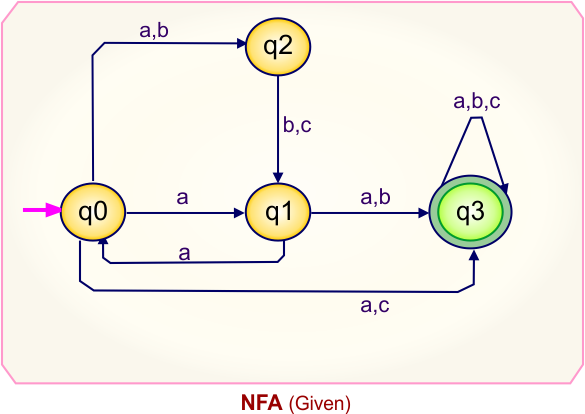
Step 01: Draw NFA Graph
The graph below represents an NFA that needs conversion into a DFA.
Step 02: Draw the NFA Transition Table.
The table below presents the transition table of the NFA derived from the given NFA.
Step 03: Conversion of NFA to DFA Transition Table
Let’s begin converting the NFA transition table to the DFA transition table.
Step 3.1: Select the first two rows of the NFA transition table to form the initial two rows of the DFA transition table below.
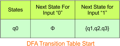
In the above DFA Table
- State Column Contains: “q0”
- Input columns contain: “q1q2q3”
Step 3.2: State “q1q2q3” is a new state because it appears in the input columns of the DFA but does not exist in the state column. Add “q1q2q3” to the state column along with its transitions.
Transition calculations at state “q1q2q3”
For input “0”
δ([q1q2q3], 0) = δ(q1, 0) ∪ δ(q2, 0) ∪ δ(q3, 0)
= {q0q3} ∪ {} ∪ {q3}
= {q0q3}
For input “1”
δ([q1q2q3], 1) = δ(q1, 1) ∪ δ(q2, 1) ∪ δ(q3, 1)
= {} ∪ {q1} ∪ {}
= {q1}
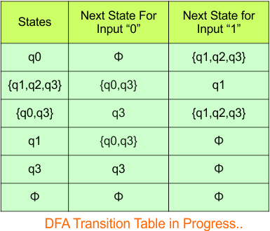
The updated DFA table is given below.
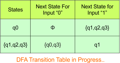
In the above DFA Table
- State Column Contains: “q0”, “q1q2q3”
- Input columns contain: “q1q2q3”, “q0q3″,”q1”
Repeat Step 3.2: States “q0q3” and “q1” are new states because they are present in the DFA’s input columns but do not exist in the state column. Add states “q0q3” and “q1” along with their transitions to the state column.
Transition calculations at state “q0q3”
For input “0”
δ([q0q3], 0) = δ(q0, 0) ∪ δ(q3, 0)
= {} ∪ {q3}
= {q3}
For input “1”
δ([q0q3], 1) = δ(q0, 1) ∪ δ(q3, 1)
= {q1q2q3} ∪ {}
= {q1q2q3}
Transition calculations at state “q1”
For input “0”
δ([q1], 0) = {q0q3}
For input “1”
δ([q1], 1) = {}
The updated DFA table is given below.
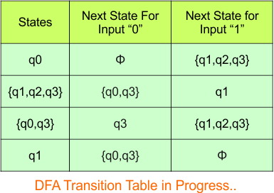
In the above DFA Table
- State Column Contains: “q0”, “q1q2q3”, “q0q3″,”q1”
- Input columns contain: “q1q2q3”, “q0q3″,”q1”, “q3”
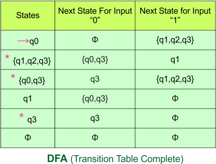
Repeat Step 3.2: “q3” is a new state because it is present in the input columns of the DFA but does not exist in the state column. Put “q3” in the state column along with their transitions.
Transition calculations at state “q3”
For input “0”
δ([q3], 0) = {q3}
For input “1”
δ([q3], 1) = {}
The updated DFA table is given below.

Repeat Step 3.2: No new states exist in the DFA table, except ϕ. The transition at “ϕ” for all inputs will always remain at “ϕ”. The updated DFA table is given below.
Step 3.3: State “q” was the final state in the NFA table. Therefore, all states will be final states where “q” appears in the DFA state column. Simply mark these states with “*” to indicate they are final states.
Here is the updated DFA table, which includes all of its final states.
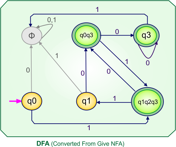
Step 4: Now draw the DFA according to the DFA transition table
The following is the converted Deterministic Finite Automaton (DFA) derived from the given Nondeterministic Finite Automaton (NFA).
NFA To DFA Example: 08
Step 01: Draw NFA Graph
The following is the NFA graph that needs to be converted to a DFA.
Step 02: Draw the NFA Transition Table.
The NFA transition table of the above NFA is given below
Step 03: Conversion of NFA to DFA Transition Table
Step 3.1: Select the first two rows of the NFA transition table, which will become the first two rows of the DFA transition table.
In the above DFA Table
- State Column Contains: “q0”
- Input columns contain: “q1q2q3”, “q2”, “q3”
Repeat Step 3.2: States “q1q2q3”, “q2”, and “q3” are new states because they are present in the DFA’s input columns but do not exist in the state column. Add states “q1q2q3”, “q2”, and “q3” along with their transitions to the state column.
Transition at state “q2”
For input “a”
δ([q2], a) = {}
For input “b”
δ([q2], b) = {q1}
For input “c”
δ([q2], c) = {q1}
Transition at state “q3”
For input “a”
δ([q3], a) = {q3}
For input “b”
δ([q3], b) = {q3}
For input “c”
δ([q3], c) = {q3}
Transition at state “q1q2q3”
For input “a”
δ([q1q2q3], a) = δ(q1, a) ∪ δ(q2, a) ∪ δ(q3, a)
= {q0q3} ∪ {} ∪ {q3}
= {q0q3}
For input “b”
δ([q1q2q3], b) = δ(q1, b) ∪ δ(q2, b) ∪ δ(q3, b)
= {q3} ∪ {q1} ∪ {q3}
= {q1q3}
For input “c”
δ([q1q2q3], c) = δ(q1, c) ∪ δ(q2, c) ∪ δ(q3, c)
= {} ∪ {q1} ∪ {q3}
= {q1q3}
Hence, the updated DFA table is given below.
In the above DFA Table
- State Column Contains: “q0″,”q1q2q3”, “q2”, “q3”
- Input columns contain: “q1q2q3”, “q2”, “q3”, “q1″,”q1q3”, “q0q3”
Repeat Step 3.2: States “q1”, “q1q3”, and “q0q3” are new states because they are present in the DFA’s input columns but do not exist in the state column. Add states “q1”, “q1q3”, and “q0q3” along with their transitions to the state column .
Transition at state “q1”
For input “a”
δ([q1], a) = {q0q3}
For input “b”
δ([q1], b) = {q3}
For input “c”
δ([q1], c) = {}
Transition calculations for state “q1q3”
For input “a”
δ([q1q3], a) = δ(q1, a) ∪ δ(q3, a)
= {q0q3} ∪ {q3}
= {q0q3}
For input “b”
δ([q1q3], b) = δ(q1, b) ∪ δ(q3, b)
= {q3} ∪ {q3}
= {q3}
For input “c”
δ([q1q3], c) = δ(q1, c) ∪ δ(q3, c)
= {} ∪ {q3}
= {q3}
Transition calculations for state “q0q3”
For input “a”
δ([q0q3], a) = δ(q0, a) ∪ δ(q3, a)
= {q1q2q3} ∪ {q3}
= {q1q2q3}
For input “b”
δ([q0q3], b) = δ(q0, b) ∪ δ(q3, b)
= {q2} ∪ {q3}
= {q2q3}
For input “c”
δ([q0q3], c) = δ(q0, c) ∪ δ(q3, c)
= {q3} ∪ {q3}
= {q3}
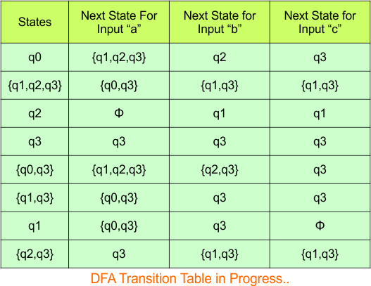
The updated DFA Table is given below
In the above DFA Table
- State Column Contains: “q0″,”q1q2q3”, “q2”, “q3”, “q0q3”, “q1q3”, “q1”
- Input columns contain: “q1q2q3”, “q2”, “q3”, “q1″,”q1q3”, “q0q3”, “q2q3”
Repeat Step 3.2: “q2q3” is a new state because it is present in the input columns of the DFA but does not exist in the state column. Put “q2q3” in the state column along with their transitions.
Transition calculations for state “q2q3”
For input “a”
δ([q2q3], a) = δ(q2, a) ∪ δ(q3, a)
= {} ∪ {q3}
= {q3}
For input “b”
δ([q2q3], b) = δ(q2, b) ∪ δ(q3, b)
= {q1} ∪ {q3}
= {q1q3}
For input “c”
δ([q2q3], c) = δ(q2, c) ∪ δ(q3, c)
= {q1} ∪ {q3}
= {q1q3}
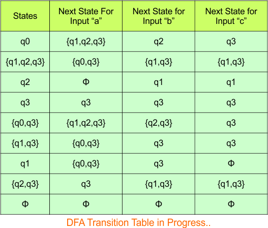
The updated DFA Table is given below
In the above DFA Table
- State Column Contains: “q0″,”q1q2q3”, “q2”, “q3”, “q0q3”, “q1q3”, “q1”, “q2q3”
- Input columns contain: “q1q2q3”, “q2”, “q3”, “q1″,”q1q3”, “q0q3”, “q2q3”
Repeat Step 3.2: No new state exists in the DFA table, except ϕ. Transition at “ϕ” against all inputs will always stay at “ϕ”. The updated DFA Table is given below
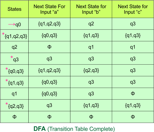
Step 3.3: At this stage, all newly generated states in the DFA table are executed successfully for their transitions, so the DFA table is ready.
Important: As “q3” was the final state in NFA Table. That’s why, all those states will be the final states where “q3” is present. Simply mark with “*” to represent the final state.
So, the following is the updated table of the DFA with its final states
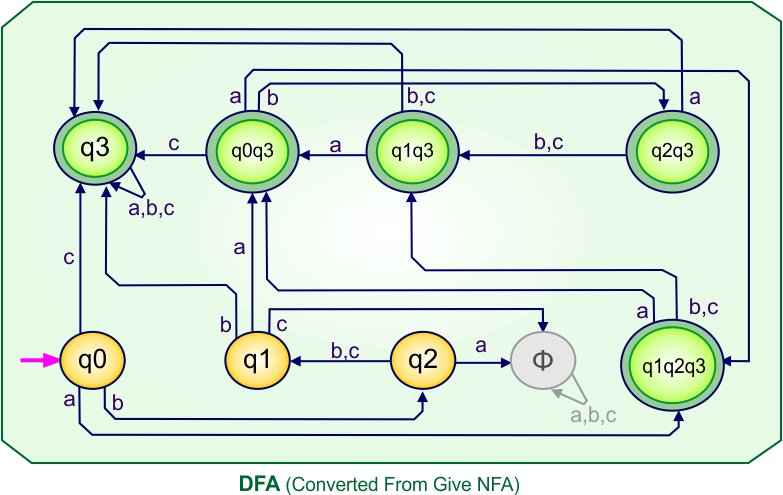
Step 4: Now draw the DFA according to the DFA Transition Table
According to the DFA transition table, we can generate the following DFA diagram
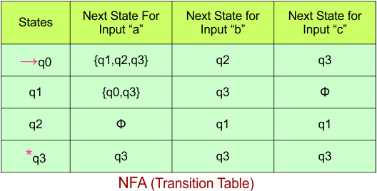
NFA To DFA Example: 09
Step 01: Draw NFA Graph
The following is the NFA graph that needs to be converted to a DFA.
Step 02: Draw the NFA Transition Table.
The NFA transition table of the above NFA is given below
Step 03: Conversion of NFA to DFA Transition Table
Step 3.1:Select the first two rows of the NFA transition table, which will become the first two rows of the DFA transition table.

In the above DFA Table
- State Column Contains: “q0”
- Input columns contain: “q1q2”, “q3”
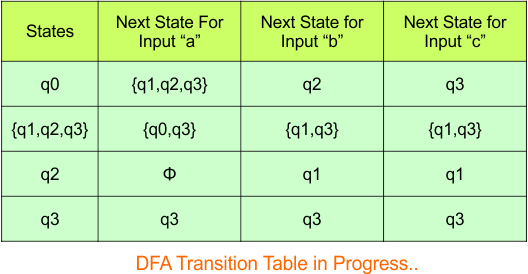
Step 3.2: States “q1q2” and “q3” are new states because they are present in the DFA’s input columns but do not exist in the state column. Add states “q1q2” and “q3” along with their transitions to the state column.
Transition calculations at state “q1q2”
For input “a”
δ([q1q2], a) = δ(q1, a) ∪ δ(q2, a)
= {q3} ∪ {}
= {q3}
For input “b”
δ([q1q2], b) = δ(q1, b) ∪ δ(q2, b)
= {q0q3} ∪ {q1}
= {q0q1q3}
For input “c”
δ([q1q2], c) = δ(q1, c) ∪ δ(q2, c)
= {q0q3} ∪ {}
= {q0q3}
For input “d”
δ([q1q2], d) = δ(q1, d) ∪ δ(q2, d)
= {} ∪ {}
= {}
Transition calculations at state “q3”
For input “a”
δ([q3], a) = {}
For input “b”
δ([q3], b) = {}
For input “c”
δ([q3], c) = {q3}
For input “d”
δ([q3], d) = {q3}
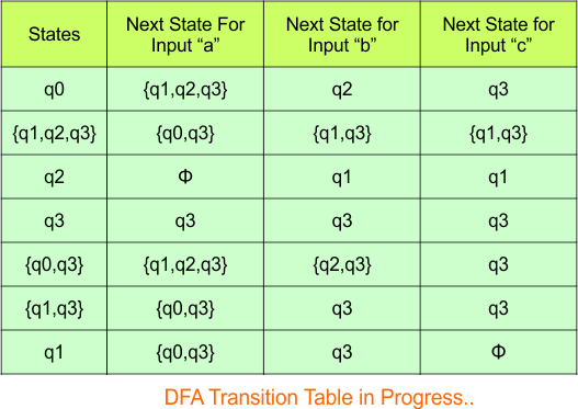
The updated DFA Table is given below

In the above DFA Table
- State Column Contains: “q0”, “q3”, “q1q2”
- Input columns contain: “q1q2”, “q3”, “q0q1q3”, “q0q3”
Step 3.2: States “q0q3” and “q0q1q3” are new states because they are present in the DFA’s input columns but do not exist in the state column. Add states “q0q3” and “q0q1q3” along with their transitions to the state column.
Transition calculations at state “q0q3”
For input “a”
δ([q0q3], a) = δ(q0, a) ∪ δ(q3, a)
= {q3} ∪ {}
= {q3}
For input “b”
δ([q0q3], b) = δ(q0, b) ∪ δ(q3, b)
= {q3} ∪ {}
= {q3}
For input “c”
δ([q0q3], c) = δ(q0, c) ∪ δ(q3, c)
= {} ∪ {q3}
= {q3}
For input “d”
δ([q0q3], d) = δ(q0, d) ∪ δ(q3, d)
= {q1q2} ∪ {q3}
= {q1q2q3}
ransition calculations at state “q0q1q3”
For input “a”
δ([q0q1q3], a) = δ(q0, a) ∪ δ(q1, a) ∪ δ(q3, a)
= {q3} ∪ {q3} ∪ {}
= {q3}
For input “b”
δ([q0q1q3], b) = δ(q0, b) ∪ δ(q1, b) ∪ δ(q3, b)
= {q3} ∪ {q0q3} ∪ {}
= {q0q3}
For input “c”
δ([q0q1q3], c) = δ(q0, c) ∪ δ(q1, c) ∪ δ(q3, c)
= {} ∪ {q0q3} ∪ {q3}
= {q0q3}
For input “d”
δ([q0q1q3], d) = δ(q0, d) ∪ δ(q1, d) ∪ δ(q3, d)
= {q1q2} ∪ {} ∪ {q3}
= {q1q2q3}
The updated DFA Table is given below

In the above DFA Table
- State Column Contains: “q0”, “q3”, “q1q2”, “q0q1q3”, “q0q3”
- Input columns contain: “q0”, “q3”, “q1q2”, “q0q1q3”, “q0q3”, “q1q2q3”
Repeat Step 3.2: “q1q2q3” is a new state because it is present in the input columns of the DFA but does not exist in the state column. Put “q1q2q3” in the state column along with their transitions.
Transition at state “q1q2q3”
For input “a”
δ([q1q2q3], a) = δ(q1, a) ∪ δ(q2, a) ∪ δ(q3, a)
= {q3} ∪ {} ∪ {}
= {q3}
For input “b”
δ([q1q2q3], b) = δ(q1, b) ∪ δ(q2, b) ∪ δ(q3, b)
= {q0q3} ∪ {q1} ∪ {}
= {q0q1q3}
For input “c”
δ([q1q2q3], c) = δ(q1, c) ∪ δ(q2, c) ∪ δ(q3, c)
= {q0q3} ∪ {} ∪ {q3}
= {q0q3}
For input “d”
δ([q1q2q3], d) = δ(q1, d) ∪ δ(q2, d) ∪ δ(q3, d)
= {} ∪ {} ∪ {q3}
= {q3}
Hence, the updated DFA table is given below.

In the above DFA Table
- State Column Contains: “q0”, “q3”, “q1q2”, “q0q1q3”, “q0q3”, “q1q2q3”
- Input columns contain: “q0”, “q3”, “q1q2”, “q0q1q3”, “q0q3”, “q1q2q3”
Repeat Step 3.2: No new state exists in the DFA table, except ϕ. Transition at “ϕ” against all inputs will always stay at “ϕ”. The updated DFA Table is given below

Step 3.3: At this stage, all newly generated states in the DFA table are executed successfully for their transitions, so the DFA table is ready.
Important: As “q3” was the final state in NFA Table. That’s why, all those states will be the final states where “q3” is present. Simply mark with “*” to represent the final state.
So, the following is the updated table of the DFA with its final states
Step 4: Now draw the DFA according to the DFA Transition Table
According to the DFA transition table, we can generate the following DFA diagram
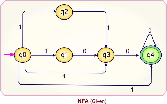
NFA To DFA Example: 10
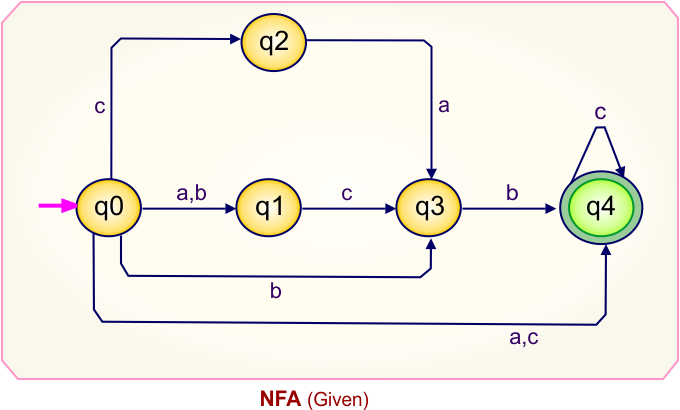
Step 01: Draw NFA Graph
The following is the NFA graph that needs to be converted to a DFA.
Step 02: Draw the NFA transition Table.
The NFA transition table of the above NFA is given below

Step 03: Conversion of NFA to DFA Transition Table
Let’s start the conversion of the NFA transition table to the DFA transition Table.
Step 3.1: Select the first two rows of the NFA transition table, which will become the first two rows of the DFA transition table given below.
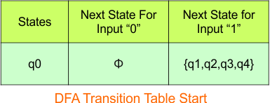
In the above DFA Table
- State Column Contains: “q0”
- Input columns contain: “q1q2q3q4″
Step 3.2: State “q1q2q3q4” is are new state because it is present in the input columns of the DFA but does not exist in the state column. Put “q1q2” in the state column along with their transitions.
Transition at state “q1q2q3q4” against
For input “0”
δ([q1q2q3q4], 0) = δ(q1, 0) ∪ δ(q2, 0) ∪ δ(q3, 0) ∪ δ(q4, 0)
= {q3} ∪ {ϕ} ∪ {q4} ∪ {q4}
= {q3q4}
For input “1”
δ([q1q2q3q4], 1) = δ(q1, 1) ∪ δ(q2, 1) ∪ δ(q3, 1) ∪ δ(q4, 1)
= {ϕ} ∪ {q3} ∪ {ϕ} ∪ {ϕ}
= {q3}
Hence, the updated DFA table is given below
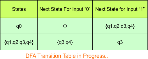
Repeat Step 3.2: State “q0” and “q1q2q3q4” exist in the state column of the DFA. However, the states “q3q4” and “q3” do not appear in the state column. Therefore, we should simply add these states to the state column.
Transition at state “q3q4” against
For input “0”
δ([q3q4], 0) = δ(q3, 0) ∪ δ(q4, 0)
= {q4} ∪ {q4}
= {q4}
For input “1”
δ([q3q4], 1) = δ(q3, 1) ∪ δ(q4, 1)
= {ϕ} ∪ {ϕ}
= {ϕ}
The transitions for “q3” are given below
For input “0”
δ([q3], 0) = {q4}
For input “1”
δ([q3], 1) = {ϕ}
Hence, the updated DFA table is given below
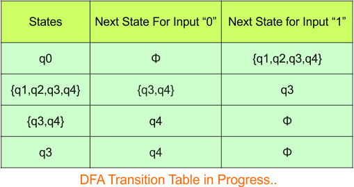
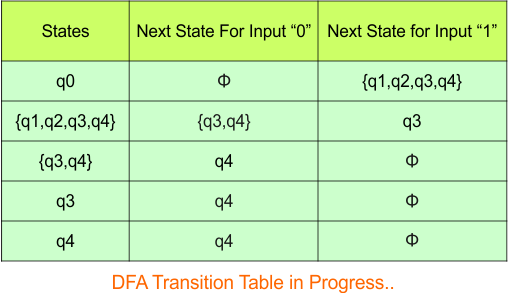
Repeat Step 3.2: State “q0”, “q3q4″,”q3” and “q1q2q3q4” exist in the state column of the DFA. However, the state “q4” do not appear in the state column. Therefore, we should simply add this state to the state column.
The transitions for “q4” are given below
For input “0”
δ([q4], 0) = {q4}
For input “1”
δ([q4], 1) = {ϕ}
The updated DFA Table is given below
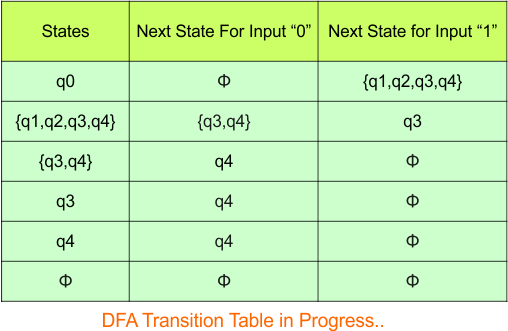
Repeat Step 3.2: No new state exists in the DFA table, except ϕ. Transition at “ϕ” against both inputs “0” and “1” is given below,
For input “0”
δ([ϕ], 0) = {ϕ}
For input “1”
δ([ϕ], 1) = {ϕ}
The updated DFA Table is given below,
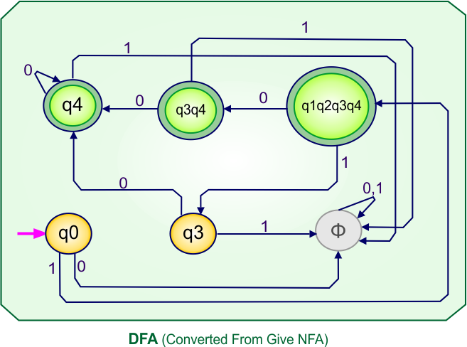
Step 3.3: At this stage, all newly generated states in the DFA table are executed successfully for their transitions, so the DFA table is ready.
Important: As q4 was the final state in NFA Table. That’s why, all those states will be the final states where q4 is present. Simply mark with “*” to represent the final state.
So, the following is the updated table of the DFA with its final states

Step 4: Now draw the DFA according to the DFA Transition Table
According to the DFA transition table, we can generate the following DFA diagram.
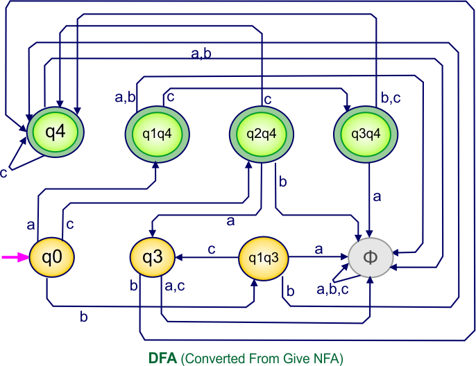
NFA To DFA Example: 11
Step 01: Draw NFA Graph
The following is the NFA graph that needs to be converted to a DFA.
Step 02: Draw the NFA Transition Table.
The NFA transition table of the above NFA is given below
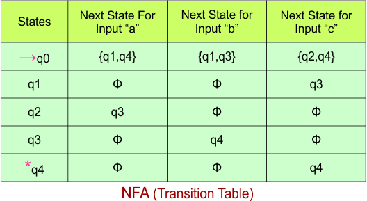
Step 03: Conversion of NFA to DFA Transition Table
Step 3.1:Select the first two rows of the NFA transition table, which will become the first two rows of the DFA transition table.
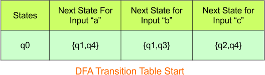
Step 3.2: Only “q0” exists in the state column of the DFA. However, the states “q1q4”, “q1q3“, and “q2q4” occur in the DFA table but do not appear in the state column. Therefore, we should simply add these states to the state column.
Transition at state “q1q4” against all inputs “a”, “b”, and “c”
For input “a”
δ([q1q4], a) = δ(q1, a) ∪ δ(q4, a)
= {ϕ} ∪ {ϕ}
= {ϕ}
For input “b”
δ([q1q4], b) = δ(q1, b) ∪ δ(q4, b)
= {ϕ} ∪ {ϕ}
= {ϕ}
For input “c”
δ([q1q4], c) = δ(q1, c) ∪ δ(q4, c)
= {q3} ∪ {q4}
= {q3q4}
Transition at state “q1q3” against all inputs “a”, “b”, and “c”
For input “a”
δ([q1q3], a) = δ(q1, a) ∪ δ(q3, a)
= {ϕ} ∪ {ϕ}
= {ϕ}
For input “b”
δ([q1q3], b) = δ(q1, b) ∪ δ(q3, b)
= {ϕ} ∪ {q4}
= {q4}
For input “c”
δ([q1q3], c) = δ(q1, c) ∪ δ(q3, c)
= {q3} ∪ {ϕ}
= {q3}
Transition at state “q2q4” against all inputs “a”, “b”, and “c”
For input “a”
δ([q2q4], a) = δ(q2, a) ∪ δ(q4, a)
= {q3} ∪ {ϕ}
= {q3}
For input “b”
δ([q2q4], b) = δ(q2, b) ∪ δ(q4, b)
= {ϕ} ∪ {ϕ}
= {ϕ}
For input “c”
δ([q2q4], c) = δ(q2, c) ∪ δ(q4, c)
= {ϕ} ∪ {q4}
= {q4}
The updated DFA Table is given below
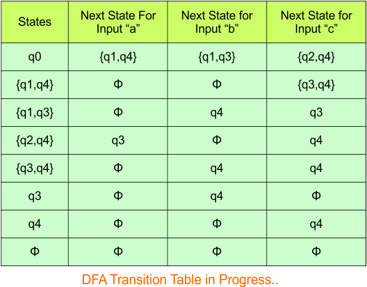
Repeat Step 3.2: State “q0”, “q1q4”, “q1q3”, and “q2q4” exist in the state column of the DFA. However, the states “q3”, “q4”, and “q3q4” appear in the DFA table but are not listed in the state column. Therefore, we should add these states to the state column.
Transition at state “q3q4” against all inputs “a”, “b”, and “c”
For input “a”
δ([q3q4], a) = δ(q3, a) ∪ δ(q4, a)
= {ϕ} ∪ {ϕ}
= {ϕ}
For input “b”
δ([q3q4], b) = δ(q3, b) ∪ δ(q4, b)
= {q4} ∪ {ϕ}
= {q4}
For input “c”
δ([q3q4], c) = δ(q3, c) ∪ δ(q4, c)
= {ϕ} ∪ {q4}
= {q4}
Transition at state “q3” against all inputs “a”, “b”, and “c”
For input “a”
δ([q3], a) = {ϕ}
For input “b”
δ([q3], b) = {q4}
For input “c”
δ([q3], c) = {ϕ}
Transition at state “q4” against all inputs “a”, “b”, and “c”
For input “a”
δ([q4], a) = {ϕ}
For input “b”
δ([q4], b) = {ϕ}
For input “c”
δ([q4], c) = {q4}
The updated DFA Table is given below

Repeat Step 3.2: No new state exists in the DFA table, except ϕ. Transition at “ϕ” against all inputs will always stay at “ϕ”. The updated DFA Table is given below
Step 3.3: At this stage, all newly generated states in the DFA table are executed successfully for their transitions, so the DFA table is ready.
Important: As q4 was the final state in NFA Table. That’s why, all those states will be the final states where q4 is present. Simply mark with “*” to represent the final state.
So, the following is the updated table of the DFA with its final states

Step 4: Now draw the DFA according to the DFA Transition Table
According to the DFA transition table, we can generate the following DFA diagram