


Deadlock Avoidance In OS
Deadlock Avoidance is a strategy used by the operating system to ensure the system never enters a deadlock state. Unlike deadlock prevention (which blocks at least one of the Coffman conditions), deadlock avoidance carefully analyzes every resource request and grants it only if it keeps the system in a safe state.
There are three major methods of deadlock avoidance (Safe State Algorithm, Banker’s Algorithm, and RAG with Claim Edges) are given below
1. Safe State Algorithm
A safe state is a condition of the system where there exists at least one safe sequence of process execution such that deadlock will never occur. Resources are allocated to each process in such a way that the deadlock never happens
Steps in Safe State Algorithm:
- Check if available resources can satisfy the Remaining Need of any process.
- If yes, assume that the process executes, finishes, and releases its resources.
- Add released resources to available resources.
- Repeat until all processes are finished.
- If all processes finish in some order, the System is in a safe state.
- If not, the system is in an Unsafe state, and deadlock is possible.
Key Formulas
- Remaining Need = Maximum Need – Allocated Instance
- Available Instance = Total Resources – Sum of All Allocated Instances
- Remaining Need ≤ Available Instance
- Available Instance = Available Instance + Allocated by Finished Process
We can derive additional formulas based on the information provided above.
|
Before proceeding to this first method, first understand safe and unsafe states in the OS. Safe StateA state where the system can allocate resources to each process in some order and still avoid deadlock. The safe state condition is
A Safe Sequence is an order of process execution. Suppose three processes (i.e., P1, P2, and P3), their possible execution order can be n!. Where “n” is the number of processes. For example, If n = 3 (processes: P1, P2, P3), then: 3!=3×2×1=6
If a system can find any one such sequence given above, it is in a safe state. Unsafe StateA state where the system cannot guarantee that all processes can complete their execution
Let’s discuss Deadlock Avoidance Techniques |
Safe State Example
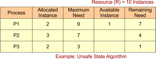
Suppose we have three processes: P1, P2, and P3, and one resource type: R (with a total of 10 instances). We need to find a safe sequence based on the information given in the table.
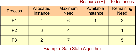
For Process P1
- Remaining Need = 2
- Available = 1
- Remaining Need <= Available = False
System moves to Next Process (P2)
For Process P2
- Remaining Need = 1
- Available = 1
- Remaining Need <=Available = True
Process P2 Get Executed and Release Its Allocated Instances (3).
Available Instance = Available Instance + Release Instance
= 1 + 3
= 4
The result is updated in the following Banker Table
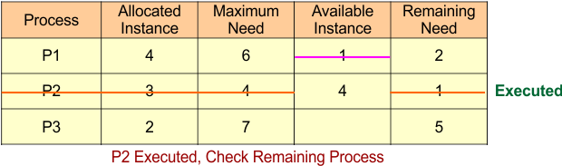
Safe Sequence Starts with Process P2, Now Check Remaining Process (P1 and P3)
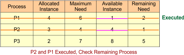
P3 can’t execute
For Process P1
- Remaining Need = 2
- Available = 4
- Remaining Need <=Available = True
Process P1 Get Executed and Release Its Allocated Instances (4).
Available Instance = Available Instance + Release Instance
= 4 + 4
= 8
The result is updated in the following Banker Table
For Process P3
- Remaining Need = 2
- Available = 8
- Remaining Need <=Available = True
Process P3 Get Executed and Release Its Allocated Instances (2).
Available Instance = Available Instance + Release Instance
= 8 + 2
= 10
The result is updated in the following Banker Table
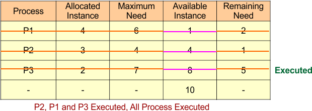
All processes are executed in the following sequence
- P2 -> P1 -> P3
So, it is a safe state, and no deadlock exists
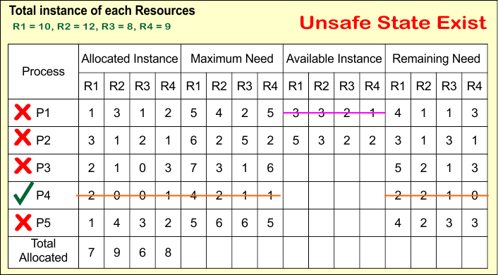
Unsafe State Example
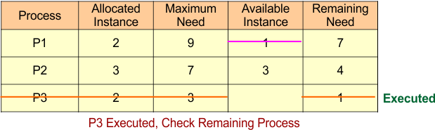
Please review the table provided below and determine whether a safe sequence exists or not.
Process P3 executed successfully because of Process P3
- Remaining Need = 1
- Available = 1
- Remaining Need <=Available = True
Process P3 Get Executed and Release Its Allocated Instances (2).
Available Instance = Available Instance + Release Instance
= 1 + 2
= 3
The result is updated in the following Banker Table
Now both P1 and P2 cannot execute because both deny the following formula
- Remaining Need <= Available
For P1
- Remaining Need (7) <= Available (3)
For P2
- Remaining Need (4) <= Available (3)
Both conditions become false
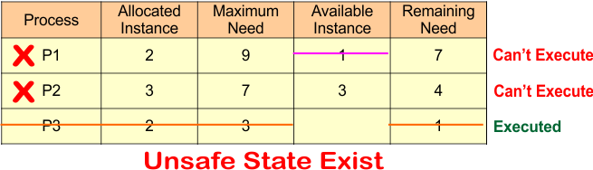
It is an unsafe state because only P3 can execute; the other processes, P1 and P2, cannot run.
Finally, we can say
- There is no safe sequence
- There is a possibility of a deadlock, not a confirmed deadlock
Tip: The Safe State Algorithm can also use different Resource Types. i.e.
|
Important: Safe State Algorithm is a concept used inside Banker’s Algorithm in OS.
2. Bankers Algorithm for Deadlock Avoidance in OS
Banker’s Algorithm is a deadlock avoidance method used in operating systems to ensure the system remains in a safe state before allocating resources to any process.
- It works well in multi-resource environments
- Prevents deadlock before it happens
- Gives a clear, saf,e or unsafe decision
Just like a banker ensures that enough cash remains to satisfy all customer withdrawals, the OS checks that it can fulfill the maximum demands of all processes, even in the worst case.
Key Formulas in Banker’s Algorithm
Formula 1: Total Allocated Instances
To find how many instances of a resource are currently in use:
Example:
If R1 is allocated to P1, P2, and P3, then:
Formula 2: Maximum Requirement
Each process has a maximum limit on what it may need.
From this, we can derive:
- Allocated = Maximum – Remaining
- Remaining = Maximum – Allocated
This allows calculation of any missing value if the other two are known.
Formula 3: Total Resource Instances
To find how many instances exist in total:
Rearranged:
-
Allocated = Total – Available
-
Available = Total – Allocated
This is used to calculate available or allocated values during initialization.
Formula 4: Safety Check Condition
Before executing any process:
-
Need comes from Formula 2.
-
Available comes from Formula 3.
This condition ensures the process can safely complete without risk of deadlock.
Formula 5: Resource Release After Completion
Once a process finishes, it releases its held resources:
This update allows the next waiting process to get the required resources.
How are these formulas used in Banker’s Algorithm?
The first three formulas are used once at the beginning to prepare the initial data (total, allocated, max, need, and available).
- Total Allocated = sum of all allocations
- Maximum Need = Allocated + Remaining
- Total Resources = Allocated + Available
Formula 4 and Formula 5 are used in a loop while checking each process:
- Check if Need ≤ Available (Formula 4)
- If yes, execute the process and update Available (Formula 5)
- Repeat for other processes until all are completed or no further process can proceed
Let discuss banker algorithm example in OS
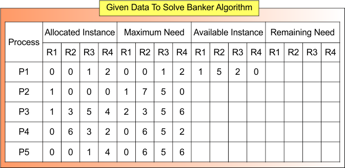
Banker’s Algorithm Example
Given values of the Banker’s Algorithm are
- Total Instance
- Allocated instance
- Maximum Need
- Available Instance
We have to find
- Total Allocated Instance
- Remaining Need
- Safe Sequence
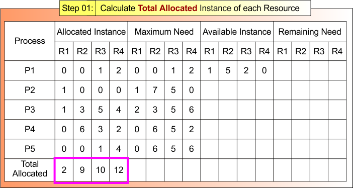
Step 01 – Calculate the Total Allocated Instance of each Resource
According to formula 01: Total Allocated Instance of Resource = Sum of Allocated Instances by all Processes
- Total Allocated to R1 = 0+1+1+0+0 = 2
- Total Allocated to R2 = 0+0+3+6+0 = 9
- Total Allocated to R3 = 1+0+5+3+1 = 10
- Total Allocated to R3 = 2+0+4+2+4 = 12
Step 01 result is updated in the following Banker Table
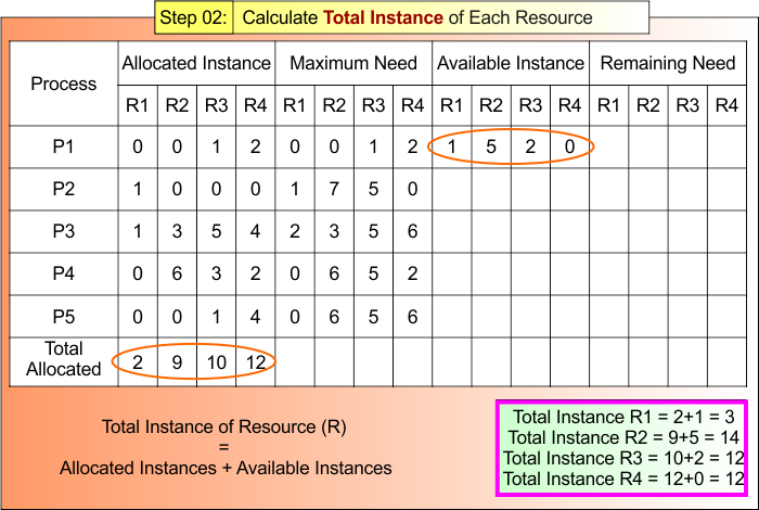
Step 02: Calculate Total Instances of Each Resource
According to formula 02:
Total Instances = Available Instances + Allocated Instances
- R1 Total Instances = 2+1 = 3
- R2 Total Instances = 9+5 = 14
- R3 Total Instances = 10+2 = 12
- R4 Total Instances = 12+0 = 12
Step 02 result is updated in the following Banker Table
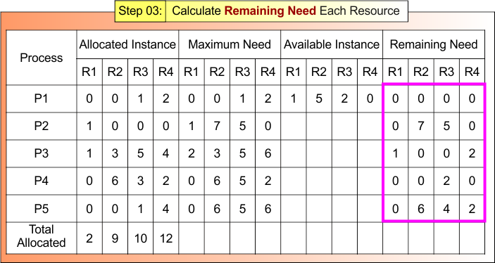
Step 03: Calculate Remaining Need for Each Resource
According to Formula 03
Remaining Need = Maximum Need – Allocated Instances
- Remaining Need R1 = Maximum Need R1 – Allocated Instances R1
- Remaining Need R2 = Maximum Need R2 – Allocated Instances R2
- Remaining Need R3 = Maximum Need R3 – Allocated Instances R3
- Remaining Need R4 = Maximum Need R4 – Allocated Instances R4
Step 03 result is updated in the following Banker Table
Step 04: Check Process Execution One by One
According to formula 04
Process Execution Formula = Remaining Need ≤ Available Instance
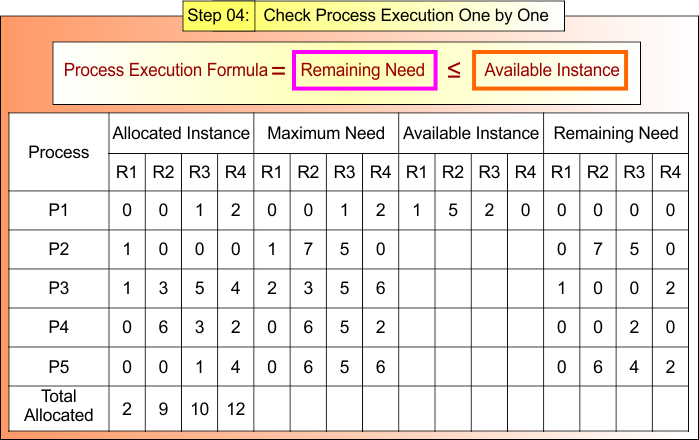
Step 4.1: Check each Process Execution
For Process P1
- Remaining Need = (0, 0, 0,0)
- Available = (1, 5, 2,0)
- Remaining Need <=Available = True
Process P1 Get Executed and Release Its Allocated Instances (0,0,1,2).
According to formula 05
Available Instance = Available (1, 5, 2,0) + Release (0,0,1,2) = (1,5,3,2)
Step 04 result is updated in the following Banker Table
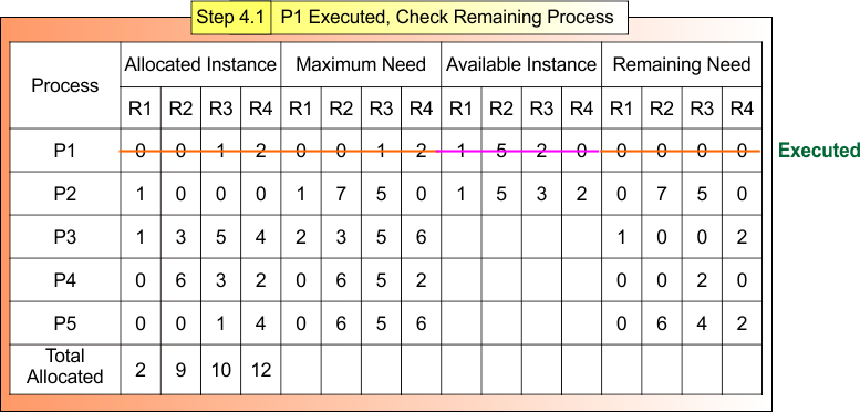
Safe Sequence Starts with Process P1
| Note: Formulas 04 and 05 are repeated until all processes are executed or check for their execution |
Step 4.2: P1 Executed, Check Remaining Process
After Step 4.1
- Process P1 is Terminated
- Available Instances (1,5,3,2)
Now,
For Process P2
- Remaining Need = (0, 7, 5,0)
- Available = (1,5,3,2)
- Remaining Need <=Available = False
For Process P3
- Remaining Need = (1, ,0, 0, 2)
- Available = (1,5,3,2)
- Remaining Need <=Available = True
Process P3 gets executed and releases its Allocated Instances (1,3,5,4).
Available Instance = Available (1,5,3,2) + Release (1,3,5,4) = (2,8,8,6)
Step 4.2 result is updated in the following Banker Table
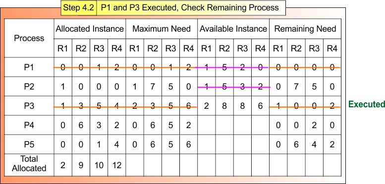
Safe Sequence P1 → P3
Step 4.3: P1 and P3 Executed, Check Remaining Process
After Step 4.2
- Process P1 and P3, Terminated
- Available Instances (2, 8, 8, 6)
Now,
For Process P4
- Remaining Need = (0,0, 2, 0)
- Available = (2, 8, 8, 6)
- Remaining Need <= Available = True
Process P4 Get Executed and Release Its Allocated Instances (0,6, 3, 2).
Available Instance = Available (2, 8, 8, 6) + Release (0,6, 3, 2) = (2, 14, 11, 8)
Step 4.3 result is updated in the following Banker Table
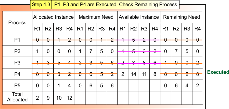
Safe Sequence P1 → P3 → P4
Step 4.4: P1, P3 and P4 Executed, Check Remaining Process
After Step 4.3
- Process P1, P3, and P4 are Terminated
- Available Instances (2,14,11,8)
Now,
For Process P5
- Remaining Need = (0,6, 4, 2)
- Available = (2,14,11,8)
- Remaining Need <= Available = True
Process P5 Get Executed and Release Its Allocated Instances (0,0,1,4).
Available Instance = Available (2,14,11,8) + Release (0,0,1,4) = (2,14,12,12)
Step 4.4 result is updated in the following Banker Table
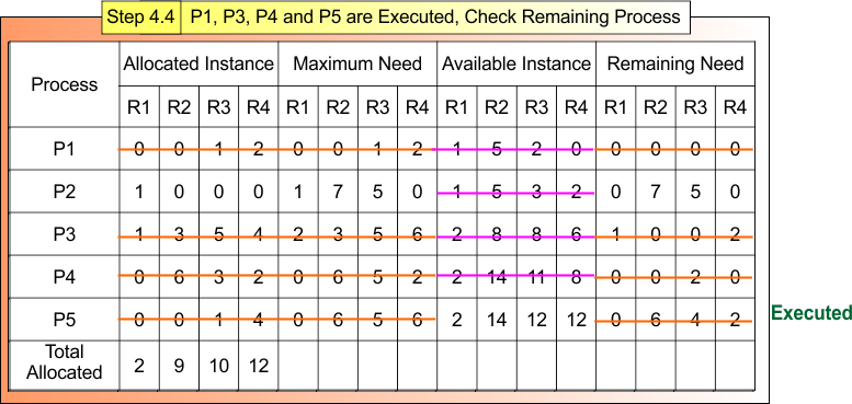
Safe Sequence: P1 → P3 → P4 → P5
Step 4.5 : P1, P3, P4 and P5 Executed, Check Remaining Process
After Step 4.4
- Process P1, P3, P4 and P5 are Terminated
- Available Instances (2,14,12,12)
Now,
For Process P2
- Remaining Need = (1, 0, 0,0)
- Available = (2,14,12,12)
- Remaining Need <= Available = True
Process P2 Get Executed and Release Its Allocated Instances (1,0,0,0).
Available Instance = Available (2,14,12,12) + Release (1,0,0,0) = (3, 14, 12,12)
All Process (P1, P2, P3, P4 and P5) are Executed . Step 4.4 result is updated in the following Banker Table
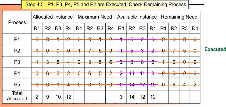
Safe Sequence: P1 → P3 → P4 → P5 → P2
If all processes are executed, then
- A safe sequence must exist
- Total allocated resources will be zero
- Total Instances of each resource = Available resources
Banker Algorithm (Unsafe State) Example:
In the given example, only Process number 4 can execute; other processes (P1, P2, P3, and P5) cannot meet the base condition of banker’s algorithm, which is
- Remaining Need <= Available
So, deadlock is possible but not guaranteed.
3. Resource Allocation Graph (RAG) with Claim Edges
A Resource Allocation Graph is a visual method to represent the current state of resource allocation in a system. It helps detect or avoid deadlocks by identifying cycles in resource requests and allocations.
Basic Components of RAG
Basic Components of RAG in deadlock avoidance are given below
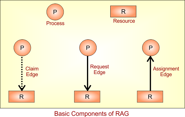
- Processes: Represented by circles (e.g., P1, P2)
- Resources: Represented by rectangles (e.g., R1, R2)
- Edges:
- Claim Edge: A Claim Edge is a dashed line drawn from a process to a resource (P —-> R)
- Request Edge: From Process to Resource (P → R)
- Assignment Edge: From Resource to Process (R → P)
| Problem with Basic RAG: The basic RAG only works when each resource has a single instance. It can detect deadlock by checking for cycles, but cannot avoid it in systems with multiple instances or dynamic requests. |
RAG Working
RAG working is given below in a descriptive diagram
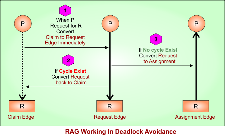
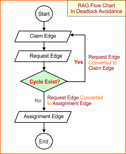
- Suppose there is a claim edge from Process (P) to Resource (R).
- As P requests R, the System Temporarily converts the claim edge to a request edge immediately
- Now, system check for a cycle in the updated Resource Allocation Graph (RAG)
- If a cycle is detected, it does not grant the request and leaves the edge as a claim edge.
- If a cycle is not found, it grants the request and converts the claim edge to a request edge.
- When the requested resource becomes available, the request edge is converted into an assignment edge, meaning the resource is now allocated to the process.
RAG Flow Chart
A flow chart of RAG is given below in a descriptive diagram
RAG Example 1: No Cycle
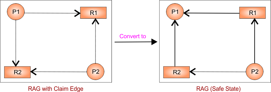
As in the above diagram of RAG safe state
- P2 → R1 (request)
- R2 → P1 (assignment)
- R1 → P1 (assignment)
But P1 is not waiting for anything — it already holds resources. So, No cycle exists, because: There is no circular chain of processes waiting
Let understand how to get it from instial RAG with claim edge to RAG (safe state)
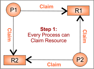
Step 1: Initial Claim Edges
- P1 may request R1 and R2
- P2 may request R1 and R2
RAG is given below
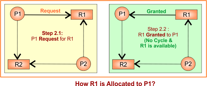
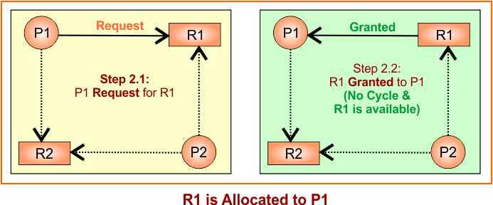
Step 2: R1 allocated to P1
Convert the claim edge to the request edge first from P1 to R1 temporarily. There is no issue with the cycle. So, Request edge is converted to an assignment (granted) edge as R1 → P1. Update RAG
Step 3: R2 allocated to P1
Convert the claim edge to the request edge first from P1 to R2 temporarily. There is no issue with the cycle. So, Request edge is converted to an assignment (granted) edge as R2 → P1 . Update RAG
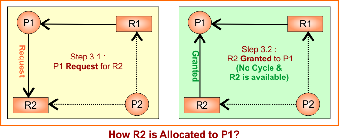
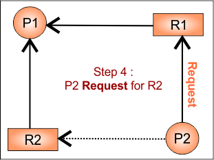
Step 4: P2 requests R1
Now, P2 tries to get R1, so we temporarily convert the claim edge P2 → R1 to a request edge. Update RAG
Example 2: Cycle Exists – Deadlock Possible
Initial Setup:
- Processes: P1, P2
- Resources: R1, R2
- Each process may request any resource in the future
Step 1: Draw Claim Edges (initial state)
Each process may need R1 and R2, so we draw claim edges (dashed lines):
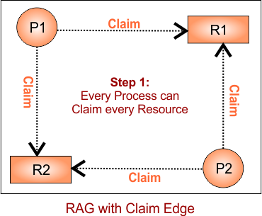
Step 2: R1 is allocated to P1
Convert the claim edge to the request edge first from P1 to R1 temporarily. There is no issue with the cycle. So, Request edge is converted to an assignment (granted) edge as R1 → P1. Update RAG
Step 3: R2 is allocated to P2
Convert the claim edge to the request edge first from P1 to R2 temporarily. There is no issue with the cycle. So, Request edge is converted to an assignment (granted) edge as R2 → P1 . Update RAG

Step 4: P2 requests R1
As P2 requests for R1, temporarily convert claim edge from P2 to R1 to request edge (P2 → R1).
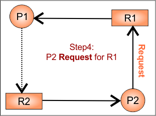
No cycle detected. So, P2 will get R1 as it is available.
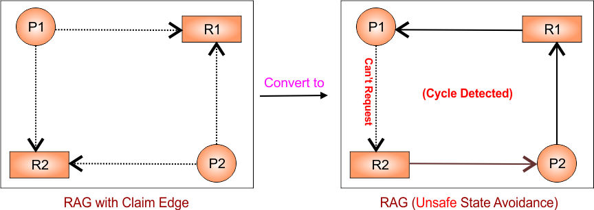
Step 5: P1 requests R2
- Temporarily convert claim edge from P1 to R2 to request edge (P1 → R2)
- System checks for cycle, cycle detected, The request is denied, The edge stays as a claim edge
Updated RAG
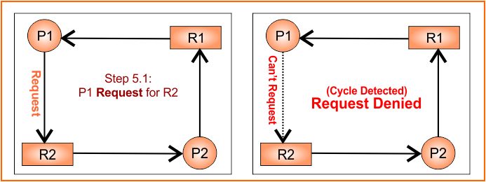
Graph remains unchanged as in Step 04
Advantages of Claim Edges in RAG
- Prevents deadlock before it occurs
- Tracks both current and future resource usage
- Maintains the system in a safe state
Limitations of Claim Edges in RAG
- Complex to implement in large-scale systems
- Requires advanced knowledge of all potential resource requests
- Cannot handle multiple instances of a resource directly
Advantages of Deadlock Avoidance
Ensures the system never enters deadlock.
Higher resource utilization compared to strict prevention.
Works dynamically, making real-time decisions.
Disadvantages of Deadlock Avoidance
Requires advance knowledge of maximum resource needs.
Complex algorithms (Banker’s Algorithm is costly in large systems).
May delay resource allocation unnecessarily.
Not suitable for highly dynamic systems.
Real-World Applications
-
Banking Systems: Loan approvals using safe/unsafe checks.
-
Database Management Systems (DBMS): Concurrency control to avoid transaction deadlocks.
-
Multiprogramming OS: Ensures fair resource allocation among multiple processes.
-
Cloud Computing & Virtualization: Avoids resource deadlock in multi-tenant environments.
Deadlock Avoidance Questions
Question No: 01
P1 required 3 resources, P2 required 4 resources, and P3 required 5 resources. How many minimum resources are required to remove deadlock?
Solution:
Minimum need of resources to avoid deadlock= (P1 resources -1) + (P2 resources -1) + (P3 resources -1) +1 = (3-1) + (4-1) + (5-1) +1= 10
Maximum of resources which can be in deadlock = Minimum need of resources to avoid deadlock -1= 10-1=9
Note: If we have three resources A,B and C. Suppose A has 5 instances, B has 1 instance and C contains 10 instance than it means we have total 16 resources. Where 5 are the type of A, 1 is type of B and 10 are type of C.
Question No 02:
Consider a system with 3 processes that share 4 instances of the same resource type. Each process can request a max of “K” instances. Find the largest value of “K,” which will always avoid deadlock _?
Case 01: Manual calculations
If a process is request for 3 resources and there are only 4 resources.
If the case is, there is an allocation of 2 resources to P1, 1 resource to P2 and 1 resource to P3 then deadlock will occur because P1 require one more resource to execute but we have nothing more to allocate.
Case 02: Through formula
Resources + Processes  > Total Demand
Resources + Processes  > (process) * (K value)
4+3>3*2 (condition true)
4+3>3*3(condition false)
So, the largest value of K will be 2 When the system is deadlock free.
If condition is true then no deadlock when condition is false then deadlock occurs. Because requesting for resource is greater than available resources. So value of K is much important
Question No: 03
Consider a system with 4 processes that share 4 instances of the same resource type. Each process can request a max of “K” instances. Find the largest value of “K,” which will always avoid deadlock __?
Case 01: Manual calculations
If every process is requesting (k=1) for one resource, and 4 resources are available. Then there will be no deadlock. But if every process is requesting for 2 resources and there are only 4 resources, then deadlock will occur. Because at the time, every process is holding one resource and waiting forthe second resource.
Case 02: Through the formula
Resources + Processes  > Total Demand
Resources + Processes  > (process) * (K value)
4+4>4*1 (condition true)
4+4>4*2(condition false)
So, the largest value of K will be 1 when the system is deadlock-free.
It was all about deadlock avoidance; next lecture, we will see deadlock detection
Question No. 4:
A system is having 3 processes; each require 2 units of resources, “R” The minimum no of units of “R” such that no deadlock will occur
Case 01: Manual Calculations
If we have only 1 resource then that one resource may allocate to any process like P1 and still P1 require 1 more resource and we have no more resource and P2 and P3 are waiting for 2, 2 resources which will execute after P1 execution but P1 never execute because P1 require 1 more resource which is not available. So deadlock will occur.
| Processes | P1 | P2 | P3 |
| Resource | 1 |
If we have 2 resources then resources are given to P1 (as the need of p1 is also 2) so it will execute successfully after P1, p2 also required 2 process and p2 also execute and same for p3.
| Processes | P1 | P2 | P3 |
| Resource | 2 |
But we have to check all possibilities of resources allocation
Like, if we have 2 resources and one resource may allocate to P1 and other may allocated to P2 and still p1 and p2 require 1 more resource to execute but we have no more resource and p3 is waiting for 2 resources which will execute after the execution of p1 or p2. But both p1 and p2 will never execute so deadlock will occur.
| Processes | P1 | P2 | P3 |
| Resource | 1 | 1 |
Now check that if we have 3 resources and three process and we allocate one resource to each process the 3 resources are used but still all process require one more resource but we have no more resource so deadlock will occur.
| Processes | P1 | P2 | P3 |
| Resource | 1 | 1 | 1 |
Now if we have 4 resources and we allocate 1 resource to each process then 3 resources are used and still need of each process is 1 resource and we have 1 resource available. Any process can get this resource and can execute. We answer is 4.
| Processes | P1 | P2 | P3 |
| Resource | 2 | 1 | 1 |
Answer: So the Answer is 4.
Case 02: Through Formula
Give the less 1 resource from the demand of every process and add 1 in previous total of resources. Explained Under
- A process required Resource=2, Minimum Resource required = 2-1=1
- B process required Resource=2, Minimum Resource required = 2-1=1
- C process required Resource=2, Minimum Resource required = 2-1=1
Add 1 in total minimum resource required = 3+1=4
So, 4 are minimum resource for deadlock avoidance when there are 3 processes and every process required 2 processes.
Max resource for deadlock is 3 where it is minimum resources required-1.